Understanding Two-Wire Proximity Sensor Fundamentals
Two-wire proximity sensors represent a fundamental and widely adopted design in industrial automation. Unlike their three-wire or four-wire counterparts, these sensors simplify wiring by combining the power supply and the switching signal into just two wires. This design inherently means the sensor must draw its operating current from the same loop that carries the load current. The core challenge for engineers lies in correctly identifying whether a two-wire sensor is configured as a PNP (sourcing) type, as this directly impacts circuit design, compatibility with programmable logic controllers (PLCs), and overall system functionality. Misidentification can lead to improper operation, potential damage to control inputs, or complete system failure. A thorough grasp of the operating principle is the first step toward accurate distinction.
The Core Principle of PNP Configuration in Two-Wire Systems
In the context of two-wire sensors, the terms "PNP" and "NPN" describe the internal switching architecture and, consequently, the direction of current flow when the sensor is active. A PNP-type two-wire proximity sensor acts as a current sourcing device. When the sensor detects a target (switches ON), it closes an internal switch that allows current to flow from the positive supply voltage (V+), through the sensor's internal circuitry and output stage, and out to the load, which is then connected to the common negative or ground (V-). The load, typically a PLC input module or a relay coil, is connected between the sensor's output wire and the ground. Therefore, in its active state, the sensor sources positive current to the load.
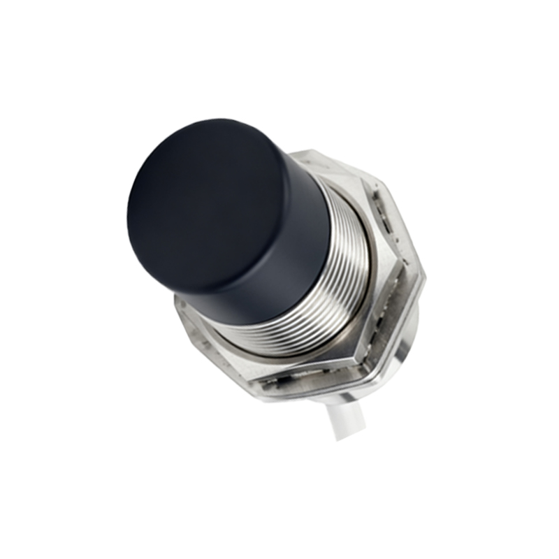
Practical Methods for Distinguishing PNP Two-Wire Sensors
Several reliable methods exist to determine if a two-wire sensor is PNP, especially when documentation is missing or markings are unclear. The most definitive approach is using a digital multimeter (DMM) set to measure DC voltage. With the sensor connected to its rated power supply (e.g., 24V DC) and the load (like a resistor simulating a PLC input) in place, measure the voltage between the sensor's output wire and the negative supply terminal. When the sensor is inactive (no target present), you will typically read a low voltage, often near 0V, as the internal switch is open. When a target activates the sensor, a PNP type will show a voltage close to the full supply voltage (e.g., ~24V) at the output wire relative to negative, indicating it is sourcing voltage. Observing the sensor's wiring diagram symbol, if available, is another key method. A PNP two-wire sensor is often symbolized with the load placed between the output and the negative rail, with an arrow pointing outward from the sensor's switching element toward the load.
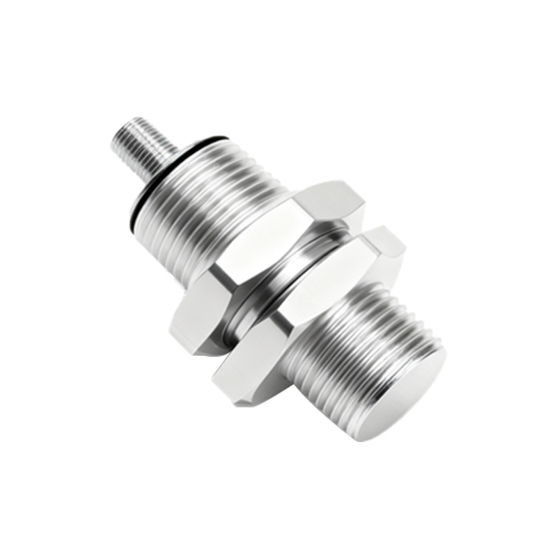
Analyzing Electrical Characteristics and Load Compatibility
The electrical behavior under load provides critical clues. A PNP two-wire sensor requires the load to be connected between its output and the negative (0V) terminal of the power supply. There is always a small voltage drop (the residual voltage or saturation voltage, typically 1.5V to 3V) across the sensor's internal switching transistor when ON. This means the voltage at the output wire will be slightly lower than the supply voltage. Measuring this "ON-state voltage" with a multimeter under load confirms operation. Furthermore, understanding load compatibility is essential. PNP two-wire sensors are designed to work with PLC input modules configured as "sinking" inputs (where the PLC's internal circuit provides a path to ground). Attempting to connect a PNP two-wire sensor to a sourcing PLC input will result in a circuit incompatibility and non-operation.
Common Application Circuits and Wiring Verification
A standard application circuit for a PNP two-wire sensor involves connecting one wire directly to the positive DC supply voltage. The other wire is connected to one terminal of the load (e.g., terminal of a relay coil or PLC digital input). The second terminal of that load is then connected to the negative DC supply or ground. This configuration creates a complete loop where the sensor controls the current flow. To verify wiring in the field, a simple test with an LED and a series resistor can be performed. Connect the anode of the LED (through a suitable resistor, e.g., 2kΩ for 24V) to the sensor's output wire and the cathode to the negative supply. For a PNP sensor, the LED will illuminate only when a target is present, visually confirming the sourcing behavior. This practical test is invaluable for troubleshooting and commissioning.