Understanding the Core Components
In industrial automation and control systems, the integration of solenoid valves and proximity sensors is fundamental for creating precise and reliable fluid or gas control loops. A solenoid valve is an electromechanically operated valve that uses an electric current through a coil to generate a magnetic field, which in turn actuates a plunger to open or close the valve orifice. Proximity sensors, on the other hand, are non-contact devices that detect the presence or absence of a target object, typically the valve's actuator or spool position indicator. Common types include inductive sensors for metallic targets and capacitive sensors for non-metallic materials. The correct wiring between these two components ensures that the control system receives accurate feedback on the valve's state—whether it is fully open, fully closed, or in a fault condition—enabling seamless process control and safety monitoring.
Key Wiring Principles and Safety Precautions
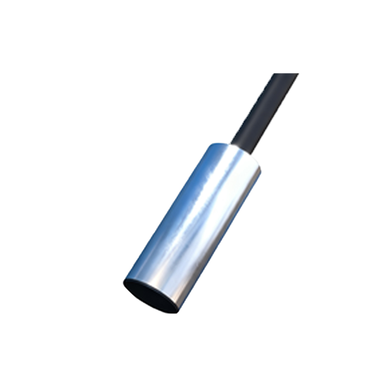
Before commencing any wiring work, it is paramount to adhere to strict electrical safety protocols. Always disconnect and lock out all power sources to the control circuit. Verify the voltage and current ratings of both the solenoid valve coil and the proximity sensor to ensure compatibility with the power supply and the programmable logic controller (PLC) or relay interface. Most industrial solenoid valves operate on standard DC (e.g., 24V DC) or AC (e.g., 120V AC) voltages. Similarly, proximity sensors are available as PNP (sourcing) or NPN (sinking) types, which determines their output signal configuration. A fundamental principle is to wire the sensor in such a way that its output signal reliably indicates the valve's physical position. This often involves mounting the sensor to detect the movement of the valve's actuator or a dedicated target flag. Proper grounding and the use of shielded cables for signal lines are critical to prevent electromagnetic interference (EMI) from affecting sensor accuracy.
Standard Wiring Configuration for Feedback Control
A typical wiring setup involves connecting the solenoid valve and the proximity sensor to a common DC power supply and a PLC digital input module. For a system using a 24V DC supply, a PNP proximity sensor, and a normally closed (NC) solenoid valve, the connection is as follows: First, connect the positive terminal (+) of the 24V DC power supply to the positive wire (typically brown) of the proximity sensor and one terminal of the solenoid valve coil. Connect the negative terminal (-) of the power supply to the common ground. The output wire (typically black) of the PNP sensor is connected to a designated digital input channel on the PLC. The other terminal of the solenoid valve coil is connected to a digital output channel on the PLC. When the PLC activates its output, current flows through the solenoid coil, energizing it and shifting the valve position. The proximity sensor, positioned to detect the valve's actuated state, will then switch its output to high (24V), sending a signal back to the PLC input to confirm the operation. This forms a basic control and feedback loop.
Implementing Dual-Sensor Monitoring for Position Verification
In critical applications where fail-safe operation is required, such as in chemical processing or emergency shutdown systems, it is common practice to use two proximity sensors: one to detect the open position and another to detect the closed position of the valve. This configuration provides positive confirmation of the valve's actual state, guarding against faults like a stuck valve or a broken mechanical linkage. Wiring involves mounting two independently adjustable sensors. Each sensor's output is wired to a separate digital input on the PLC. The control logic is programmed to interpret the signals; for instance, both sensors showing "off" might indicate a valve in transit or a fault condition. The wiring must ensure that the sensors do not interfere with each other and that their sensing ranges are precisely adjusted to avoid false triggering. This redundant monitoring significantly enhances system reliability and diagnostic capability.
Troubleshooting Common Wiring and Operational Issues
Even with correct initial wiring, issues may arise during operation. If the proximity sensor fails to detect the valve position, first check the sensor's alignment and distance to the target; it must be within its specified sensing range. Verify the power and output connections with a multimeter. Ensure the sensor's output type (PNP/NPN) matches the PLC input type (sourcing/sinking). A common mistake is mixing PNP and NPN wiring, which results in no signal. For the solenoid valve, failure to actuate could point to a wiring fault, a burnt coil, or insufficient voltage. Listen for an audible click upon energization. Use a clamp meter to check the inrush and holding current of the coil. Additionally, ensure that