Fundamental Operating Principle
Inductive proximity sensors are non-contact electronic devices designed to detect the presence of metallic objects without physical contact. The core of their operation lies in an oscillator circuit that generates a high-frequency electromagnetic field at the active face of the sensor. When a metallic target enters this oscillating field, eddy currents are induced on the surface of the target. These eddy currents draw energy from the sensor's oscillator, resulting in a measurable reduction in the oscillation amplitude. An integrated evaluation circuit continuously monitors this amplitude. Once the amplitude drop surpasses a predefined threshold, the sensor's output state switches, signaling the detection of an object. This robust principle allows for reliable detection of ferrous metals like steel and iron, as well as non-ferrous metals such as aluminum, brass, and copper, albeit with different sensing distances due to varying material conductivity and permeability.
Key Technical Characteristics and Specifications
Understanding the key specifications is crucial for proper sensor selection. The rated operating distance, or nominal sensing range (Sn), is a fundamental parameter defined for a standard target. This target is typically a square of mild steel (Fe360) with a thickness equal to the sensor's rated distance or 1mm, whichever is greater. It's vital to note that the actual sensing distance can vary with different metals; for instance, aluminum may reduce the effective range to approximately 40-50% of Sn. Another critical specification is the hysteresis, expressed as a percentage of Sn. Hysteresis is the difference between the switch-on point as the target approaches and the switch-off point as it moves away, preventing output chatter when a target is at the exact sensing limit. Other essential specs include switching frequency (how many detections per second), repeat accuracy, temperature range, housing material (often nickel-plated brass or stainless steel), and protection class (e.g., IP67 for dust and temporary immersion).

Common Output Configurations and Wiring
Inductive sensors are available in several output configurations to interface with control systems. The two primary types are DC 3-wire and AC/DC 2-wire versions. DC 3-wire sensors are the most common, offering separate connections for power supply positive, power supply negative, and the switched output signal. They come in two logic types: NPN (sinking) and PNP (sourcing). NPN outputs switch the negative (0V) line to the load, common in Asian and some European systems, while PNP outputs switch the positive voltage line, prevalent in North America and many European countries. AC/DC 2-wire sensors are wired in series with the load, simplifying installation but requiring a minimum load current to operate correctly. Additionally, analog output versions (4-20 mA or 0-10 V) provide a continuous signal proportional to the distance to the target, useful for positioning or monitoring applications.
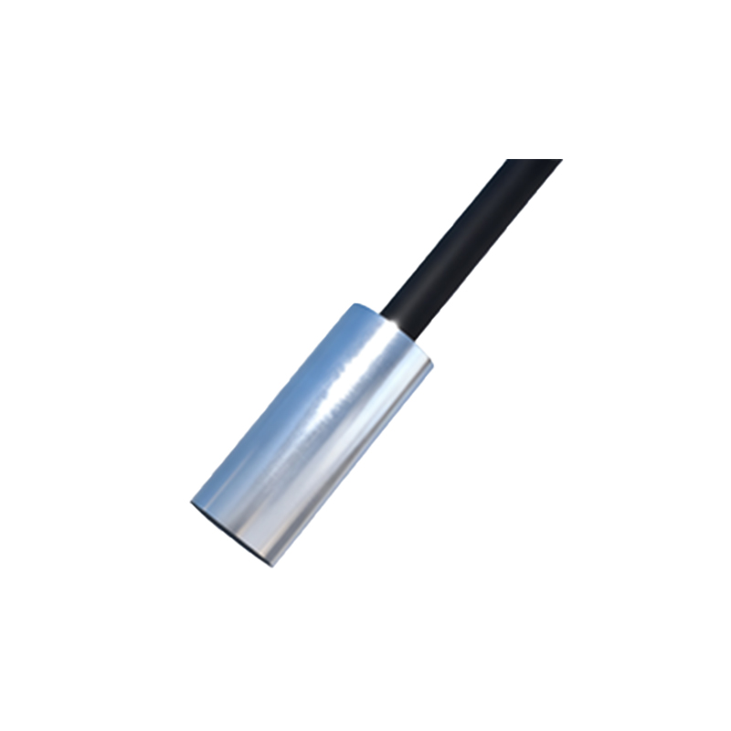
Major Application Areas in Industrial Automation
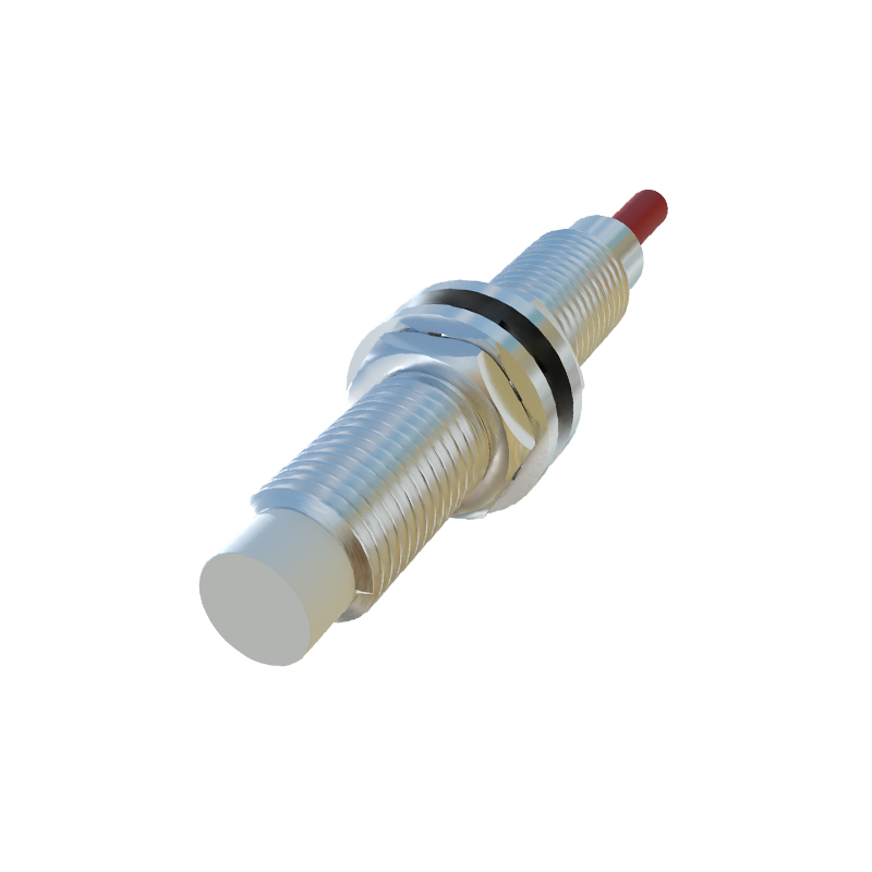
The robustness and reliability of inductive proximity sensors make them indispensable across numerous industrial sectors. In automotive manufacturing, they are extensively used for part presence verification, robotic end-effector positioning, and counting components on conveyor lines. Within packaging machinery, they detect metal components on high-speed fillers, cappers, and labelers. In metalworking and CNC machining, these sensors provide precise position feedback for tool changers, monitor spindle orientation, and confirm workpiece clamping. Material handling systems rely on them for pallet detection, conveyor jam prevention, and elevator positioning. Their ability to function in harsh environments—resistant to dirt, dust, oils, and coolants—ensures stable performance where optical sensors might fail.
Installation Considerations and Environmental Factors
Correct installation is paramount for optimal performance and longevity. A primary consideration is maintaining adequate clearance around the sensor's sensing face. Flush-mountable sensors can be installed embedded in metal without loss of sensing range, whereas non-flush sensors require a clear zone around the face, as specified by the manufacturer, to prevent interference from the surrounding metal mounting structure. Sensors should also be spaced sufficiently apart from each other to avoid mutual interference of their electromagnetic fields. Environmental factors such as extreme temperatures, strong electromagnetic fields from welding equipment, or aggressive chemicals can affect performance. Selecting a sensor with an appropriate housing material (e.g., stainless steel for corrosive environments) and a high enough IP rating for the application is essential for reliable operation.
Guidelines for Sensor Selection and Sizing
Selecting the right inductive proximity sensor involves a systematic evaluation of the application requirements. First, identify the target material and determine the necessary effective sensing distance, factoring in material-specific reduction factors. Next, consider the required switching frequency to ensure it meets or exceeds the process speed. The