Understanding Inductive Proximity Sensor Basics
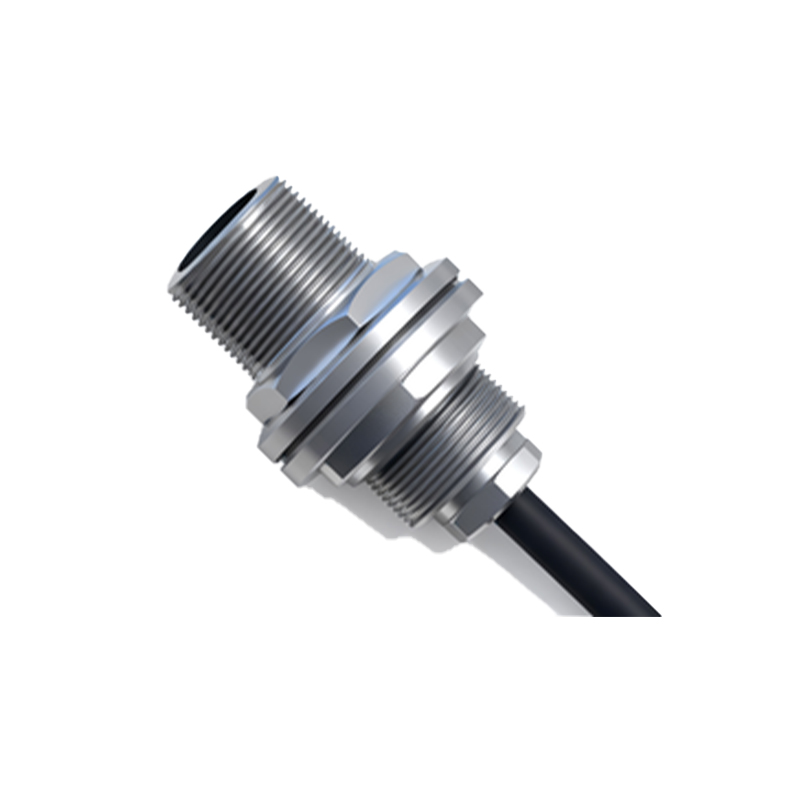
Inductive proximity sensors are fundamental components in industrial automation, used for non-contact detection of metallic objects. Before wiring, it's crucial to understand their operating principle. These sensors generate an electromagnetic field. When a metal target enters this field, it causes a change in the sensor's oscillation amplitude, which is then converted into a switching signal. They typically come in two main types based on output configuration: 2-wire, 3-wire (PNP or NPN), and occasionally 4-wire versions. The 3-wire DC sensors are the most common in modern control systems. The housing is usually made of metal or robust plastic, with an LED indicator to show the switching status. Always begin by consulting the sensor's datasheet for its specific voltage range (commonly 10-30V DC), output type, and current rating to ensure compatibility with your power supply and controller (PLC).
Essential Tools and Safety Precautions
Gather the necessary tools before starting: appropriate screwdrivers, wire strippers, a multimeter for verification, and the correct gauge of cable. Safety is paramount. Always disconnect and lock out all power sources to the control panel or machine before beginning any wiring work. Verify that the power is off using a multimeter. Ensure the working environment is dry and free from conductive metal chips or dust that could cause short circuits. Wear appropriate personal protective equipment (PPE). Identify the sensor's specifications label, noting the operating voltage, output type (e.g., PNP normally open), and the function of each wire, typically color-coded: brown for positive (+V), blue for negative (0V/Common), and black for the output signal.
Wiring a 3-Wire DC Inductive Proximity Sensor
The 3-wire sensor is the industry standard. For a PNP (sourcing) sensor, connect the brown wire to the positive terminal of your DC power supply (e.g., +24V). Connect the blue wire to the negative or 0-volt terminal of the same power supply. The black wire is the switched output. In a PNP sensor, this output will supply positive voltage when activated. Connect the black wire to the input channel of your PLC, relay, or other load. The other side of that load must then be connected back to the power supply's negative (blue) line to complete the circuit. For an NPN (sinking) sensor, the wiring is similar, but the blue wire connects to negative, brown to positive, and the black output wire sinks current to negative when activated. The load is connected between the positive supply and the black wire.
Connecting a 2-Wire AC/DC Sensor
Two-wire sensors are simpler but require careful consideration of the load. They can operate on AC or DC and are wired in series with the load and the power supply. There is no polarity for AC versions. For DC types, observe polarity if marked. One wire connects to one side of the power source, and the other wire connects to one terminal of the load (like a PLC input). The other terminal of the load must connect back to the opposite side of the power source. A critical point is the "leakage current." Even when switched off, a small current flows through the sensor. The connected load must have a low enough impedance to prevent this leakage current from falsely activating it. A bypass resistor may be required per the sensor manual.
Integrating with a Programmable Logic Controller (PLC)
Integration with a PLC is a common application. For a 3-wire PNP sensor, connect its black output wire to a specific PLC digital input point (e.g., I0.0). Connect the PLC input's common terminal for that group (often labeled M or COM) to the DC power supply's negative (0V). This creates a path: +24V -> Sensor (when active) -> PLC Input -> PLC Common -> 0V. The PLC input will read a logic HIGH (1) when the sensor detects a target. For an NPN sensor, the PLC common for the input group typically needs to be connected to positive voltage (+24V). The sensor's black wire connects to the PLC input, which is then pulled low (to 0V) when active, registering a logic LOW (0) or HIGH depending on PLC configuration.
Testing and Troubleshooting Common Issues
After wiring, apply power cautiously. The sensor's LED should illuminate when a metal target is within its sensing range. Use a multimeter to measure the voltage between the output wire (black)