Understanding Proximity Switch Sensor Basics
Proximity switch sensors are essential components in industrial automation, detecting the presence or absence of objects without physical contact. These sensors operate based on electromagnetic fields, capacitive effects, or inductive principles, depending on the type. The circuit board within the sensor manages signal processing and output control, ensuring reliable performance in harsh environments. Proper wiring is critical to avoid malfunctions, such as false triggers or damage to the sensor. Engineers must consider factors like voltage ratings, load compatibility, and environmental conditions when designing or installing these systems. A clear wiring diagram simplifies this process, reducing errors during setup and maintenance.
Components of the Circuit Board
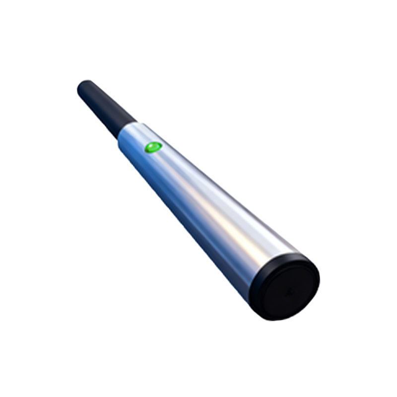
The circuit board of a proximity switch sensor typically includes several key components. These consist of an oscillator circuit to generate the detection field, a demodulator to process signals, and an output stage with transistors or relays. Additionally, there are protection circuits against overvoltage, reverse polarity, and short circuits. Connectors or terminal blocks are integrated for wiring external devices like PLCs or actuators. Understanding each component's function helps in troubleshooting and optimizing the sensor's performance. For instance, the oscillator's frequency determines detection range, while the output stage defines switching capabilities.
Wiring Diagram Interpretation
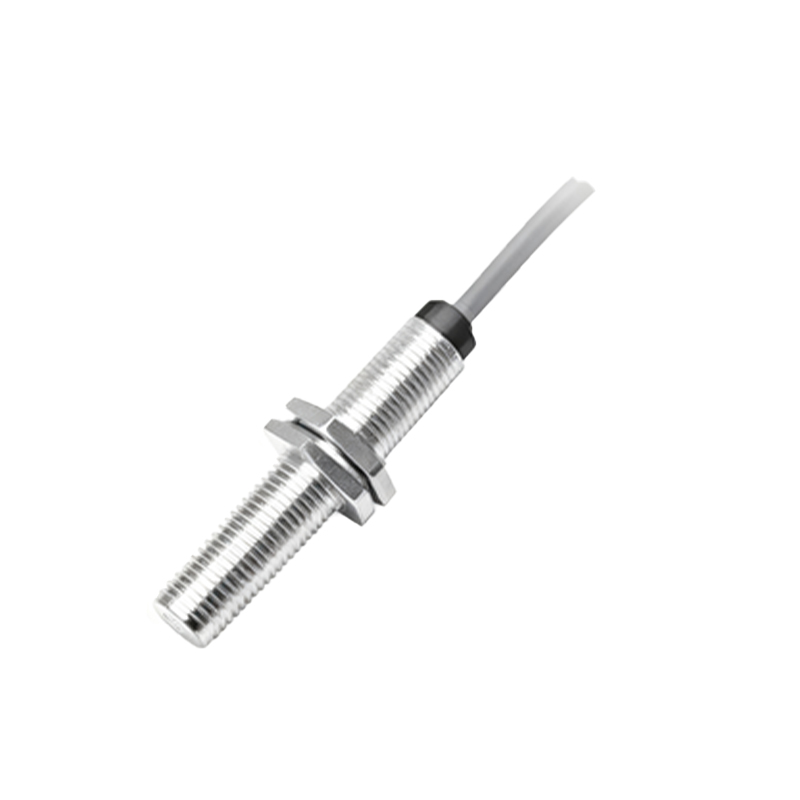
A standard wiring diagram for a proximity switch sensor circuit board illustrates connections for power supply, output signals, and ground. Typically, it shows three wires: brown for positive voltage (e.g., 10-30V DC), blue for negative or ground, and black for the output signal. Some models include additional wires for complementary outputs or diagnostics. The diagram specifies pin assignments and labeling, such as V+, V-, and OUT. Engineers should follow manufacturer guidelines to match wire colors with terminals, ensuring correct polarity. Incorrect wiring can lead to sensor failure or safety hazards, so double-checking the diagram before installation is advised.
Step-by-Step Wiring Procedure
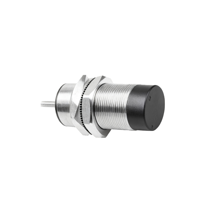
Begin by disconnecting power to prevent electrical shocks. Identify the sensor's wiring terminals based on the circuit board diagram. Connect the brown wire to the positive power source and the blue wire to the ground. Attach the black output wire to the load device, such as a relay or PLC input. Use shielded cables in noisy environments to minimize interference. Secure connections with appropriate terminals and avoid loose wires that could cause short circuits. After wiring, apply power and test the sensor with a target object to verify proper operation. Document the setup for future reference, noting any adjustments made during installation.
Common Wiring Mistakes and Solutions
Frequent errors in wiring proximity switch sensors include reversed polarity, incorrect voltage application, and poor grounding. Reversed polarity can damage the circuit board, so always verify wire colors against the diagram. Using an incompatible voltage may cause overheating or erratic behavior; check the sensor's specifications before connecting. Inadequate grounding leads to electromagnetic interference, affecting signal accuracy. To resolve these, use a multimeter to test connections and ensure proper insulation. Regular maintenance, such as inspecting for corrosion or wear, also prevents long-term issues. Consulting the manufacturer's troubleshooting guide can aid in diagnosing complex problems.
Advanced Wiring Configurations
For complex systems, proximity switch sensors may require advanced wiring setups. This includes daisy-chaining multiple sensors to a single power supply or integrating them into networked systems like IO-Link. In such cases, the circuit board diagram will show additional terminals for communication lines or auxiliary outputs. Engineers must calculate total current draw to avoid overloading the power source. Using junction boxes or distribution panels can organize wiring and improve reliability. Always adhere to industrial standards, such as IEC 60947, for safety and compatibility. Testing each sensor individually before full integration ensures the entire system functions seamlessly.
Maintenance and Safety Tips
Regular maintenance of proximity switch sensor wiring involves checking for loose connections, frayed wires, and environmental damage like moisture ingress. Clean the circuit board periodically to remove dust or debris that could affect performance. Follow lockout-tagout procedures during maintenance to ensure worker safety. When replacing sensors, refer to the original wiring diagram to avoid discrepancies. Keep documentation updated with any modifications. Implementing these practices extends the sensor's lifespan and reduces downtime in automated processes. Always prioritize safety by wearing protective gear and using insulated tools when handling electrical components.