Introduction to Magnetic Interference in Sensing
In industrial automation and control systems, proximity sensors are indispensable for non-contact detection of metallic objects. However, their reliable operation is frequently challenged by electromagnetic interference (EMI), particularly from magnetic fields. These fields, emanating from sources like motors, transformers, solenoids, and high-current cables, can induce false triggering, shift sensing distances, or cause complete sensor failure. Understanding the mechanisms of this interference and implementing effective countermeasures is critical for ensuring system stability, safety, and precision in demanding environments such as automotive manufacturing, metal processing, and robotic assembly lines.
Operating Principles and Vulnerability
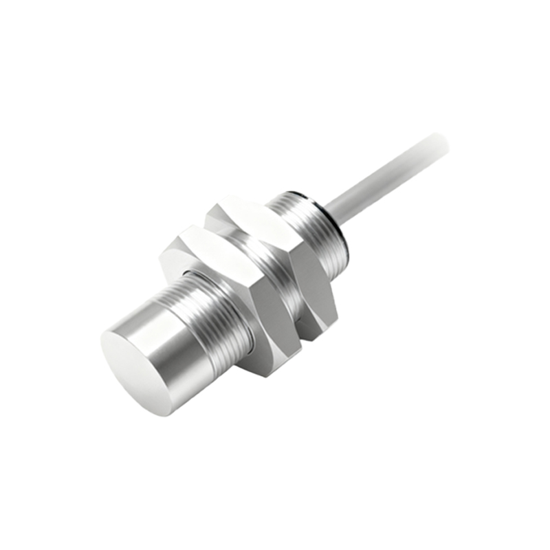
Most inductive proximity sensors operate on the principle of electromagnetic induction. An internal oscillator generates a high-frequency alternating magnetic field from a coil wound around a ferrite core. When a metallic target enters this field, eddy currents are induced, causing a change in the oscillator's amplitude or frequency, which is detected by the threshold circuit to switch the output. This very principle makes them susceptible to external magnetic fields. An external magnetic field can couple with the sensor's internal coil, inducing additional voltages or altering the magnetic flux in the core. This parasitic effect can mimic or mask the presence of a target, leading to erroneous signals. The degree of vulnerability depends on the sensor's design, the strength and frequency of the external field, and its relative orientation.
Primary Sources of Magnetic Interference
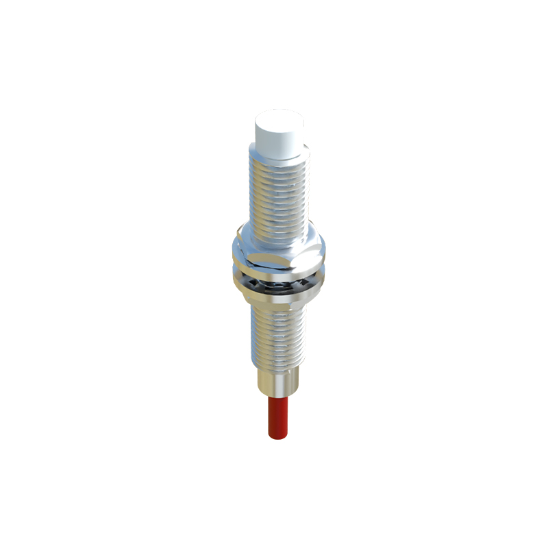
Identifying potential sources is the first step in mitigation. Common culprits include AC/DC motors and generators, which produce strong alternating or pulsating fields. Welding equipment, especially during arc initiation, generates intense, broadband electromagnetic noise. Power transformers and chokes are significant sources of 50/60 Hz magnetic fields. Actuators like solenoids and relays create transient fields during switching. Furthermore, high-current busbars or power cables, when routed close to sensors, can produce substantial magnetic fields proportional to the current flow. Even adjacent sensors can interfere with each other if mounted too closely without proper shielding.
Design-Level Countermeasures
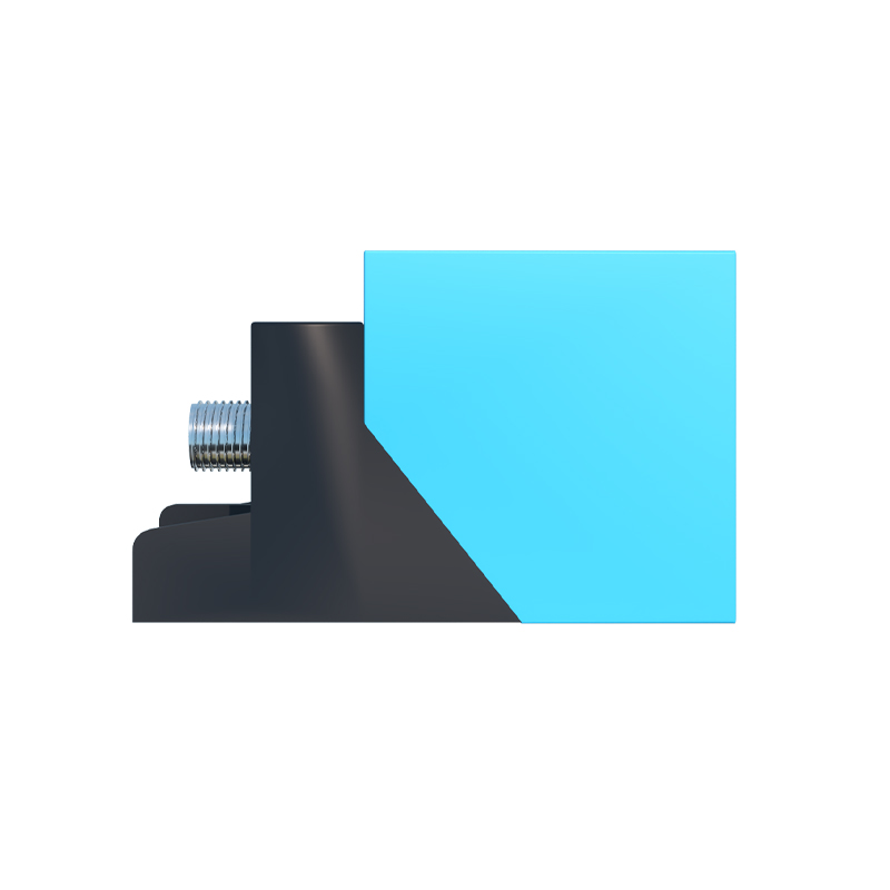
Manufacturers employ several design strategies to enhance immunity. Magnetic shielding using high-permeability materials like mu-metal or specialized alloys is highly effective for low-frequency fields. These materials provide a low-reluctance path, diverting external flux away from the sensitive core. For higher frequencies, conductive shielding (e.g., copper or aluminum) that works on the principle of eddy current cancellation is used. Differential sensing technology utilizes two coils in a balanced configuration. An external uniform field affects both coils equally, resulting in a common-mode signal that is rejected by the detection circuit, while a target creates a differential signal. Advanced signal processing, including frequency modulation of the oscillator and digital filtering algorithms, allows the sensor to distinguish its own signal from external noise. Selecting sensors with a higher operating frequency can sometimes help, as they may be less susceptible to lower-frequency industrial interference.
Installation and Configuration Best Practices
Proper installation is as crucial as sensor selection. Maintaining adequate physical separation from known interference sources is the simplest and most effective rule. Refer to manufacturer datasheets for minimum distancing guidelines. When routing sensor cables, avoid running them parallel to power cables; cross them at right angles if necessary and maintain separation. Use shielded cables, ensuring the shield is properly grounded at the control panel end (typically single-point grounding to avoid ground loops). For sensors in extremely noisy environments, employing a dedicated, clean DC power supply with sufficient filtering can prevent conducted interference. Mounting sensors on non-ferromagnetic mounting brackets prevents the concentration of stray magnetic fields. Configuring sensors with a slight hysteresis or delay can help ignore brief interference pulses.
System-Level Shielding and Grounding
In severe cases, system-level approaches are required. Localized shielding involves enclosing the sensor or the entire machine section in a grounded metallic enclosure. The enclosure material and thickness must be chosen based on the frequency of the interference. Implementing a robust, star-point grounding scheme for the entire control system minimizes ground potential differences and reduces common-mode noise. Using galvanic isolation for sensor signals, either through opto-isolators in the controller or via isolated sensor amplifiers, breaks ground loops and prevents noise propagation. For critical applications, consider systems with diagnostic capabilities that can monitor signal quality and alert operators to potential interference issues before they cause faults.
Verification and Testing Procedures
After implementing countermeasures, verification is essential. Functional testing under normal and worst-case operating conditions should be performed. A simple test involves bringing the suspected interference source (e.g., a powered motor) near the installed sensor while monitoring its output with an oscilloscope for glitches or instability. Specialized equipment like Helmholtz coils can generate calibrated magnetic fields for standardized immunity testing