Introduction to Metal Proximity Sensor Replacement
Metal proximity sensors are critical components in industrial automation, detecting the presence of metallic objects without physical contact. Over time, these sensors may fail due to environmental factors, mechanical damage, or simply wear and tear. Knowing how to properly remove and replace a failed sensor is an essential skill for maintenance technicians and engineers. This guide provides a systematic, safety-first approach to ensure a successful and reliable replacement, minimizing machine downtime and preventing potential hazards. The process involves preparation, safe removal, installation of the new unit, and final verification.
Essential Safety Precautions and Preparation
Before beginning any work, the foremost priority is safety. Always follow Lockout/Tagout (LOTO) procedures to isolate the machine or production line from all energy sources—electrical, pneumatic, and hydraulic. Verify the isolation using a multimeter to ensure no voltage is present at the sensor's connection point. Gather all necessary tools, including appropriate wrenches, screwdrivers, and a multimeter. Obtain the correct replacement sensor, confirming its specifications (e.g., sensing range, output type—PNP/NPN, NO/NC, voltage rating, and housing size) match the original. Having the machine's electrical schematic or manual on hand is highly recommended for reference.
Step 1: Disconnecting the Electrical Wiring
Locate the faulty proximity sensor on the machine. Most industrial sensors use a quick-disconnect connector or a terminal block housed in a separate junction box. If it's a quick-disconnect type, simply press the release tab and pull the connector straight off the sensor's pigtail leads. For hard-wired sensors, you will need to open the junction box or the sensor's own housing. Carefully note or photograph the existing wiring configuration. Using a screwdriver, loosen the terminal screws and remove the wires one by one. It is crucial to label each wire according to its function (e.g., +V, Output, 0V) using tape or markers to ensure correct reconnection later.
Step 2: Removing the Mounting Hardware
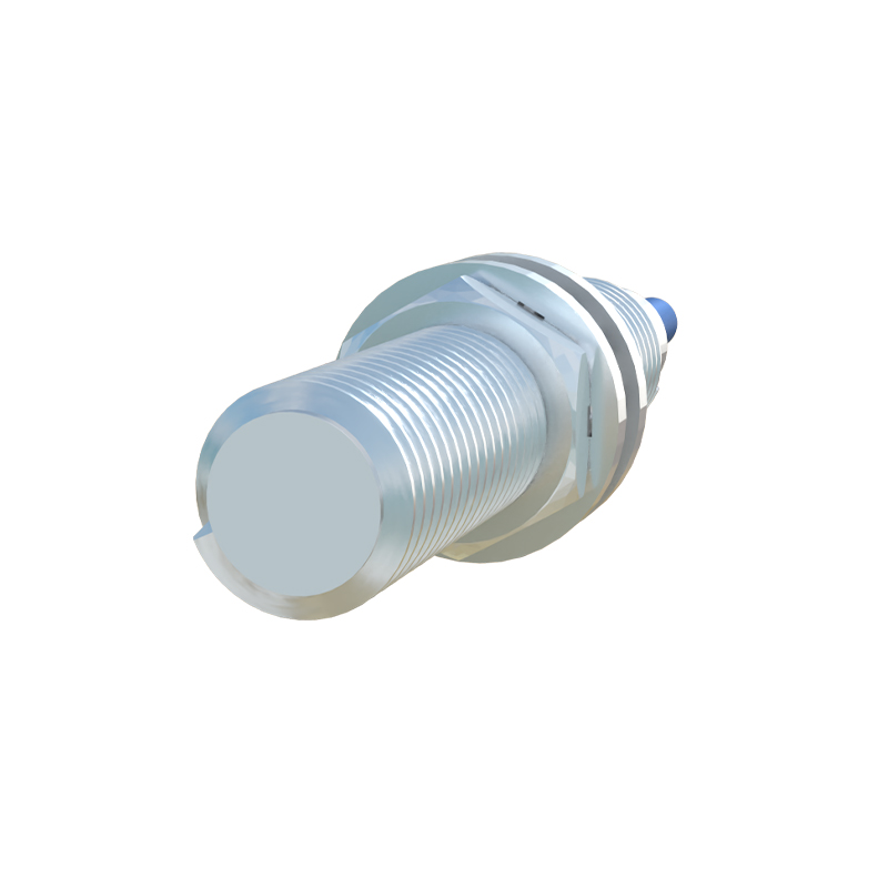
Once the sensor is electrically isolated, proceed to remove its physical mounting. Metal proximity sensors are typically secured with one or two locknuts on a threaded barrel style, or with brackets using bolts. For barrel sensors, hold the sensor body firmly to prevent it from spinning, and use a wrench to loosen the locknut(s) on the mounting thread. Some sensors may require a specific size of deep socket. For bracket-mounted sensors, unscrew the bolts securing the bracket. Carefully extract the sensor from its mounting location, being mindful not to damage the sensing face or the mounting threads.
Step 3: Installing the New Proximity Sensor
Begin by inspecting the new sensor and its mounting location. Clean any debris, metal shavings, or dirt from the mounting hole or bracket. For a threaded barrel sensor, first screw the provided locknut(s) onto the sensor's threads. Insert the sensor into the mounting hole and hand-tighten. The sensing face must be positioned correctly relative to the target object. Refer to the sensor's datasheet for the proper sensing distance and alignment. Once positioned, use a wrench to tighten the locknut securely, ensuring the sensor does not rotate. Avoid overtightening, as this can damage the housing. For bracket mounts, position the sensor in the bracket and tighten the bolts to the manufacturer's specified torque.
Step 4: Reconnecting the Electrical Connections
With the sensor physically installed, reconnect the wiring. If using a quick-disconnect, simply push the connector onto the sensor's leads until it clicks into place. For hard-wired connections, refer to your labels or photograph. Strip the wire ends if necessary and insert them into the correct terminals on the new sensor or its junction box. Typically, brown or red wires connect to the positive supply (+V), blue or black wires to the negative or common (0V), and black or white wires to the output signal. Tighten each terminal screw securely to ensure a good electrical connection and prevent vibration-induced loosening.
Step 5: Testing and Commissioning
Do not restore power until you have double-checked all connections and mounting. After restoring power using proper LOTO reversal procedures, you must test the sensor's functionality. Bring the target metal object (the actuator or part the sensor is designed to detect) within its specified sensing range. Use a multimeter to measure the voltage at the output wire, or observe the sensor's indicator LED (if equipped). The output should change state (e.g., from 0V to 24V for a PNP sensor)