Understanding Proximity Switch Fundamentals
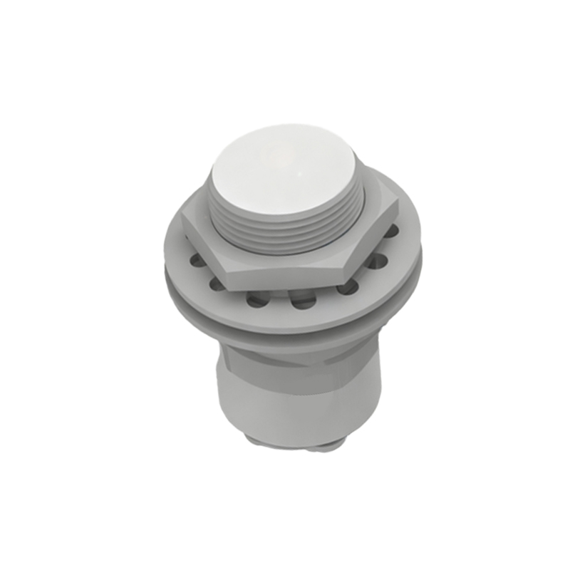
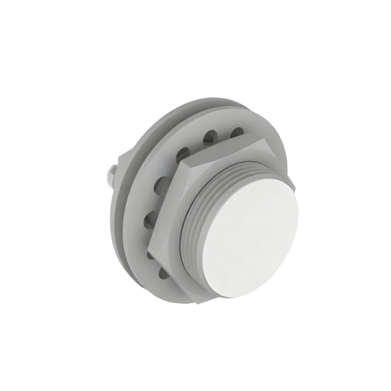
Proximity switch sensors are indispensable components in modern industrial automation, providing non-contact detection of metallic or non-metallic objects. Unlike mechanical limit switches, they operate without physical contact, leading to enhanced reliability, longer service life, and higher operational speeds. The core principle involves generating an electromagnetic field or beam. When a target object enters this field, it causes a change in the sensor's oscillation amplitude, capacitance, or light reception, which is then converted into an electrical signal to trigger a switch. Primary types include inductive (for metals), capacitive (for various materials including liquids), ultrasonic, and photoelectric sensors. Selecting the correct type is the foundational step before any detection methodology is applied, as each technology has distinct operational parameters and material sensitivities.
Visual Inspection and Physical Verification
Before employing electronic tools, a thorough visual and physical inspection is paramount. Begin by checking the sensor's housing for any signs of physical damage, cracks, or corrosion. Ensure that the mounting is secure and properly aligned; even a slight misalignment can cause detection failures. Verify the cleanliness of the sensing face, as accumulated dirt, oil, or metal shavings can attenuate the sensing field. Inspect the cable and connector for wear, cuts, or loose connections. For threaded barrel sensors, confirm that the lock nut is tightened to specification to prevent movement. This step, though basic, often reveals simple issues that can be rectified quickly, preventing unnecessary downtime and more complex diagnostic procedures.
Electrical Parameter Testing with a Multimeter
A digital multimeter is a fundamental tool for diagnosing proximity sensor issues. First, ensure power is disconnected for safety. Set the multimeter to the resistance (ohms) function to check the continuity of the sensor's coil (for inductive types) or internal circuitry. An open circuit indicates a failed sensor. Next, with power applied according to the sensor's specifications (typically 10-30V DC), measure the output voltage. For a normally open (NO) sensor, the output voltage should be near the supply voltage when no target is present and drop close to 0V when a target is within the sensing range. For a normally closed (NC) sensor, the opposite is true. Inconsistent or incorrect voltage readings point to a potential fault in the sensor's output stage or switching element.
Functional Testing with Target Simulation
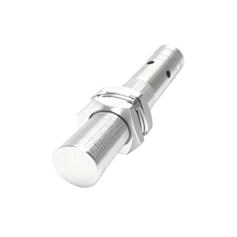
The most direct method to verify sensor operation is functional testing using a standard target. The target material and size should match the sensor's datasheet specifications. Slowly bring the target toward the sensing face along the axis of the sensor. Use a non-metallic tool if necessary to avoid influencing inductive sensors. Observe the sensor's indicator LED (if present) and simultaneously monitor the output with a multimeter or a PLC input module. Note the exact distance at which the sensor switches. Compare this "actual sensing distance" to the "rated sensing distance" listed in the technical data. A significant reduction (e.g., less than 80% of rated) suggests performance degradation, potentially due to aging components, a weakened oscillator, or environmental interference.
Oscilloscope Analysis for Signal Integrity
For intermittent faults or issues related to switching speed and signal quality, an oscilloscope is an invaluable diagnostic instrument. Connect the oscilloscope probe to the sensor's output wire and ground. Trigger the sensor repeatedly with a target. Observe the waveform of the output signal. A healthy solid-state output should show a clean, rapid transition between high and low states with minimal noise or ringing. Excessive noise on the signal line can cause false triggering in the controller. Check for slow rise or fall times, which may indicate a failing output transistor or excessive load capacitance. This analysis is crucial in high-speed counting or positioning applications where signal integrity is critical for system accuracy.
Environmental Factor and Interference Assessment
Proximity sensors often malfunction due to environmental factors rather than internal failure. Systematically assess the operating environment. For inductive sensors, check for the presence of other metals in close proximity that could cause shielding or create an extended sensing field. For capacitive sensors, variations in humidity or the presence of conductive dust can affect performance. Electrical interference from nearby motors, variable frequency drives (VFDs), or welding equipment can induce noise. Ensure proper grounding of the sensor housing and the machine. Consider using shielded cables and routing sensor wires away from power lines. In harsh environments, verify the sensor's IP (Ingress Protection) rating is adequate for the levels of dust and moisture present.
Diagnostic Procedures Using Programmable Logic Controllers (PLCs)
In an integrated automated system, the PLC serves as a powerful diagnostic tool. Monitor the input status associated with the proximity sensor