Understanding Proximity Sensor Short Circuits
A short circuit in a proximity sensor is a critical fault condition where an unintended low-resistance path forms between electrical conductors. This typically occurs between the power supply lines (V+ and V-) or between a signal output line and either supply rail. In industrial environments, such faults are often caused by physical damage to the sensor cable, such as crushing, cutting, or abrasion against sharp metal edges. Moisture ingress, chemical corrosion, or insulation breakdown due to excessive heat can also create a conductive bridge between wires. Internally, a short can result from component failure, solder bridging, or contamination on the sensor's printed circuit board. The immediate symptom is usually the tripping of a protective circuit breaker or fuse on the power supply line, or the sensor and its connected system becoming completely unresponsive. In some cases, a constant "on" or "off" signal may be output regardless of target presence. Identifying a short circuit is the first step before any repair can be attempted.
Immediate Safety and Diagnostic Steps
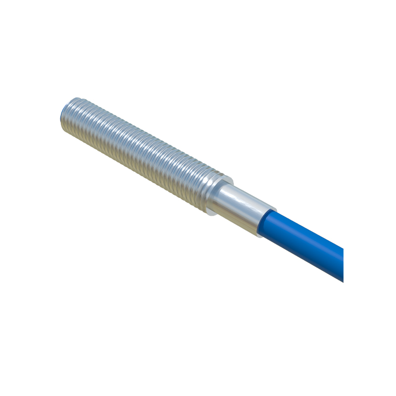
Safety is paramount. Before any hands-on work, always lock out and tag out (LOTO) the main power source to the machine or control panel supplying the sensor. Use a multimeter set to the resistance (ohms) or continuity mode. Disconnect the sensor from its controller or PLC to isolate it. First, measure the resistance between the brown (typically +V) and blue (typically 0V or -) wires. A reading very close to zero ohms (e.g., 0.5Ω) indicates a direct short between the supply lines. Next, check between each supply wire and the black (signal output) wire. A low resistance reading here suggests a short to the output. Also, check the resistance from each wire to the sensor's metal housing (ground). Any low reading indicates a short to ground. These measurements will confirm the presence and location of the short circuit. Visually inspect the entire cable length, connector, and sensor housing for obvious damage, burns, or melted areas.
Repairing Cable and Connector Shorts
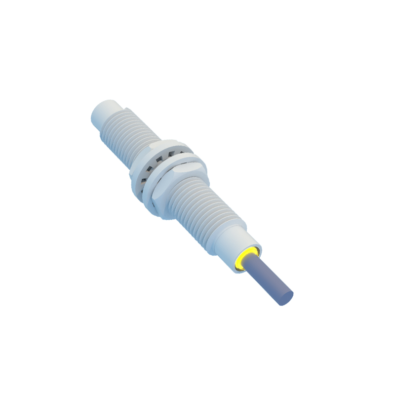
If the short is located in the cable or at the connector, repair is often feasible. For localized cable damage, the damaged section can be cut out. Strip back the insulation from the healthy cable ends on both sides. Use solder and heat-shrink tubing with adhesive lining for a robust, waterproof connection, matching each wire color precisely. Alternatively, use a properly rated industrial splice connector. Ensure the repair maintains the cable's original shielding integrity; reconnect the shield drain wire if present. If the short is at a molded connector, replacement is usually necessary. Source an identical, IP-rated connector kit. Carefully wire the new connector following the pinout diagram, ensuring no stray strands cause new shorts. After repair, re-measure resistance to verify the short is eliminated before reconnecting power.
Addressing Internal Sensor Short Circuits
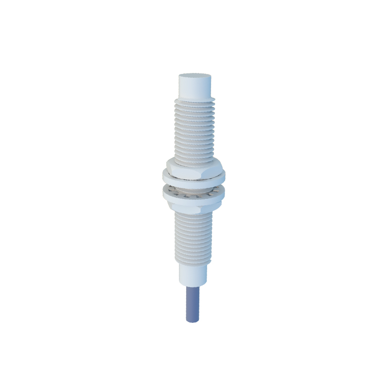
An internal short within the sensor housing often requires component-level repair or sensor replacement. For non-hermetic models, you can carefully open the housing. Look for signs of burnt components, carbon tracking, or corroded solder joints on the PCB. A common failure point is the output switching transistor or IC. Using a multimeter in diode mode, you can test these semiconductors. However, such repairs require advanced electronics skills and the right spare parts. For most maintenance technicians in an industrial setting, the more reliable and time-efficient solution is to replace the entire sensor. The downtime cost often outweighs the repair attempt. When selecting a replacement, ensure the sensing type (inductive, capacitive, magnetic), sensing distance, output type (PNP/NPN, NO/NC), voltage rating, and housing size/thread match the original specifications exactly.
Prevention and Best Practices
Preventing short circuits extends sensor life and improves system reliability. Use high-quality, shielded cables with appropriate mechanical robustness (e.g., PUR or PVC jacket) for the environment. Install cables securely within cable carriers or conduits, especially in areas with moving parts or high risk of abrasion. Avoid tight bending radii that can stress internal wires. For sensors in wet or washdown areas, ensure they have a suitable IP rating (e.g., IP67, IP69K) and that cable entries are properly sealed with gland fittings. Implement proper electrical protection at the system level, such as fast-acting fuses or electronic circuit breakers rated just above the sensor's operating current. These will isolate a fault quickly, preventing damage from cascading. Regularly include sensor and cable inspection in the preventive maintenance schedule, looking for early signs of wear, cracked insulation, or loose connections.