Understanding Proximity Sensor Fundamentals
Proximity sensors are non-contact electronic devices designed to detect the presence or absence of an object within a specific sensing range without physical contact. They operate by emitting an electromagnetic field, beam, or ultrasonic waves and analyzing changes in the return signal or field. The core principle hinges on the interaction between the sensor's emitted energy and the target object. Common types include inductive sensors for detecting metallic objects, capacitive sensors for both metallic and non-metallic materials, photoelectric sensors using light beams, and ultrasonic sensors employing sound waves. Selecting the correct type is the foundational step in their application, dictated by the target material, required sensing distance, environmental conditions, and the desired output signal.
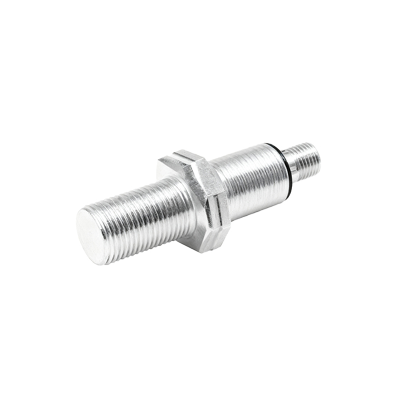
Selecting the Appropriate Sensor Type
The application dictates the sensor choice. Inductive proximity sensors are ideal for machine automation to detect metal parts like gears or pistons, offering high repeatability and resistance to dirt and oil. Capacitive sensors can detect liquids, plastics, and wood, making them suitable for level detection in tanks or material handling. Photoelectric sensors, with their longer ranges, are perfect for object counting on conveyor belts or detecting transparent films. Ultrasonic sensors excel in harsh environments with dust or fog and are used for distance measurement or pallet detection. Key selection parameters include nominal sensing distance (Sn), the recommended reduction factor for different metals (for inductive types), response frequency, output type (PNP/NPN, NO/NC), and housing material (e.g., nickel-plated brass, stainless steel) for chemical resistance.
Proper Installation and Mounting Practices
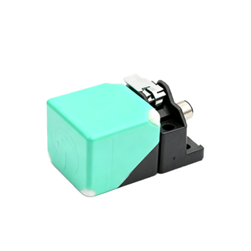
Correct installation is critical for reliable operation. First, ensure the sensor is mounted securely to prevent vibration-induced errors. For flush-mountable sensors, they can be installed embedded in a metal bracket, but note that the sensing range is reduced. Non-flush sensors require a clear space around the sensing face—typically one to two times the sensor diameter—to achieve their stated range. Always refer to the manufacturer's datasheet for precise mounting dimensions. Avoid mounting multiple inductive sensors directly opposite each other to prevent mutual interference; maintain a minimum lateral separation. For photoelectric sensors, ensure the lens is clean and aligned correctly with the reflector or receiver. Protect sensors from physical damage and excessive stress on cables by using strain relief.
Electrical Wiring and Connection Guidelines
Accurate wiring is paramount for safety and functionality. Most modern 3-wire DC sensors have Brown (V+), Blue (V-), and Black (output) wires. Always connect the sensor to a power supply within its specified voltage range (e.g., 10-30V DC). Incorporate a protective fuse in the circuit. For PNP (sourcing) sensors, the load (e.g., PLC input, relay) is connected between the output wire and the negative supply. For NPN (sinking) sensors, the load connects between the output and positive supply. Ensure the load current does not exceed the sensor's maximum switching capacity. Shielded cables are recommended for long runs or in electrically noisy environments, with the shield grounded at one end. Always implement proper grounding techniques to minimize electromagnetic interference.
Configuring Sensitivity and Setting the Sensing Distance
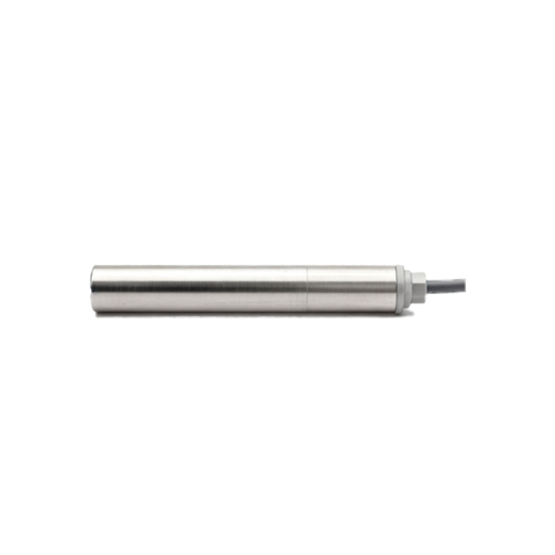
Many proximity sensors feature a potentiometer or teach-in function for sensitivity adjustment. This is crucial for detecting small objects, ignoring background materials, or compensating for environmental factors like temperature drift. For capacitive sensors, adjust sensitivity to ignore the container wall while detecting the material inside. When setting the sensing distance, operate within 50-80% of the nominal range (Sn) to account for supply voltage fluctuations, temperature changes, and part tolerances. Never use the absolute maximum range for critical applications. For applications requiring precise positioning, use sensors with analog current or voltage outputs (4-20mA, 0-10V) that provide a continuous signal proportional to distance.
Integration with Control Systems
The sensor's output signal must be correctly interfaced with the control system, such as a Programmable Logic Controller (PLC), relay, or counter. Verify the input characteristics of the PLC module (sinking vs. sourcing) match the sensor's output type. Use intermediate relays if the sensor's switching capacity is insufficient for the load. For high-speed counting or positioning, select sensors with a fast response time and connect them to high-speed counter inputs on the PLC. Implement software debouncing or use sensors with built-in hysteresis to prevent signal chatter from vibrating targets. Clearly document the I/O assignment in the electrical schematic for maintenance and troubleshooting.
Troubleshooting Common Operational Issues
Systematic troubleshooting resolves most field issues. If a sensor fails to detect, first check power and wiring connections. Use a multimeter