Understanding 4-Wire Linear Proximity Sensors
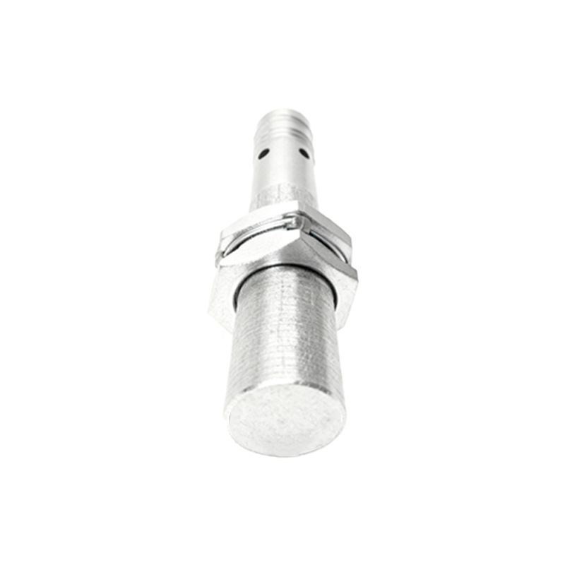
A 4-wire linear proximity sensor is a critical component in industrial automation, designed to detect the presence or position of metallic objects without physical contact. Unlike simpler 2-wire sensors, the 4-wire configuration provides enhanced functionality and precision. This type of sensor typically consists of two separate circuits: one for power supply and another for the output signal. The additional wires allow for a clear separation between the sensor's operating power and its switching output, which minimizes interference and improves signal integrity. Commonly used in applications such as machine tool positioning, conveyor systems, and robotic arms, these sensors offer high repeatability and reliability. Understanding the basic operating principle—often based on electromagnetic induction or eddy current effects—is essential before proceeding with wiring. The sensor generates an electromagnetic field, and when a metallic target enters this field, it causes a change in oscillation amplitude or frequency, which is then converted into an electrical signal.
Wire Identification and Color Coding Standards

Correct identification of each wire is the foundation of a successful installation. While color codes can vary by manufacturer, a common international standard is often followed. Typically, the four wires are designated as follows: Brown wire is connected to the positive supply voltage (V+), usually ranging from 10-30V DC. The blue wire is connected to the negative supply or ground (0V). The black wire is the output signal line, which provides a switched positive voltage (PNP configuration) when the target is detected. The white wire is often a complementary output or a second signal line; in many standard PNP sensors, it serves as the normally closed (NC) output, while the black wire is the normally open (NO) output. It is imperative to consult the specific sensor's datasheet, as some models may use alternative colors like yellow or green. Misidentification can lead to sensor damage or malfunction in the control system. Always verify the wiring diagram provided by the manufacturer before making any connections.
Step-by-Step Wiring Procedure
Begin by ensuring the power source is completely disconnected to prevent electrical shock or short circuits. Prepare the sensor cable by stripping the insulation from the ends of each wire appropriately. First, connect the brown wire to the positive terminal of your DC power supply. The blue wire should be connected to the negative terminal or common ground of the power supply. This completes the power circuit, energizing the sensor's internal electronics. Next, connect the output wires to your controller, such as a Programmable Logic Controller (PLC) or relay module. For a standard PNP (sourcing) sensor, connect the black wire to the digital input channel of the PLC. The white wire, if used as an NC output, can be connected to a separate input if required by the application. Ensure that the PLC input is compatible with the sensor's output voltage. Finally, connect the sensor's metal housing to a proper earth ground using the designated grounding terminal, if available, to shield against electromagnetic interference.
Configuring Output Types: PNP vs. NPN
The choice between PNP and NPN output configurations is crucial and depends on the control system's requirements. In a 4-wire sensor, this is often predefined, but some models allow configuration. PNP (positive switching) sensors are more common in Europe and many industrial settings. In this setup, the black output wire switches the positive voltage to the load when activated. The load (e.g., PLC input) is connected between the output and ground. Conversely, NPN (negative switching) sensors, prevalent in some regions, switch the negative side. Here, the output wire provides a path to ground when activated. The 4-wire design simplifies this by clearly separating the supply and output circuits, reducing the risk of incorrect sourcing or sinking connections. Always match the sensor's output type with your PLC's input specifications. Using a PNP sensor with an NPN-compatible input, or vice versa, will result in a non-functional system.
Integration with PLCs and Control Systems
Integrating a 4-wire linear proximity sensor into a modern PLC system enhances automation precision. After physical wiring, configuration within the software is necessary. Assign the correct input address in the PLC programming software corresponding to the physical terminal where the sensor's black (or white) wire is connected. Given the clean signal from the separate output circuit, these sensors typically do not require additional signal conditioning. However, in environments with high electrical noise, such as near variable frequency drives, using shielded cable and grounding the shield at one end is recommended. The sensor's output can be used for high-speed counting, precise positioning feedback, or as a