Introduction to Proximity Sensors
Proximity sensors are vital components in modern electrical and automation systems. These non-contact devices detect the presence or absence of an object within a specified range without any physical contact. Operating on various principles such as electromagnetic, capacitive, ultrasonic, or optical, they convert information about the presence of a target into an electrical signal. This fundamental capability makes them indispensable for tasks ranging from simple object detection to complex position sensing in industrial machinery, automotive systems, and consumer electronics. Their reliability, speed, and durability, stemming from the lack of mechanical wear, set them apart from traditional limit switches.
Core Functions and Applications
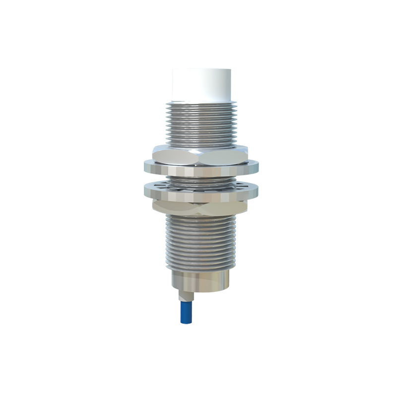
The primary function of a proximity sensor is to detect, often with high precision and repeatability. This detection triggers a control action within a circuit or system. Common applications include determining the position of a machine part, counting objects on a conveyor belt, monitoring liquid levels, ensuring safety by detecting personnel in hazardous zones, and facilitating automated assembly processes. For instance, in an automated packaging line, a proximity sensor can detect when a product is in position for sealing, sending a signal to initiate the next step. In automotive applications, they are used for parking assistance systems, detecting obstacles near the vehicle. Their ability to function in harsh environments—resistant to dirt, oil, and vibrations—further expands their utility in heavy industry.
Operating Principles Overview
Different types of proximity sensors function based on distinct physical principles. Inductive proximity sensors are the most common in industrial settings for detecting metallic objects. They generate an electromagnetic field; when a metal target enters this field, it induces eddy currents, causing a change in the sensor's oscillation amplitude, which is then converted into a switching output. Capacitive sensors can detect both metallic and non-metallic materials (like plastic, wood, or liquids) by measuring changes in capacitance caused by the target altering the sensor's electrostatic field. Ultrasonic sensors use sound waves, measuring the time for an echo to return, making them suitable for distance measurement and level detection. Photoelectric sensors employ a light beam (visible or infrared) and detect interruptions or reflections of that beam.
Electrical Symbols and Schematic Representation
In electrical schematics and ladder diagrams, proximity sensors are represented by standardized symbols, crucial for clear communication among engineers and technicians. While variations exist, the most common symbol resembles a standard switch symbol (a line opening or closing a circuit) but is enclosed within a diamond shape. This diamond indicates a sensor or a device that is actuated by an external physical condition rather than manual operation. The specific type is often denoted by additional markings or labels next to the symbol. For example, an inductive sensor might be labeled "INDPROX" or simply "PROX." The output switching element (normally open (NO) or normally closed (NC) contacts) is drawn adjacent to the sensor symbol. It is essential to consult the specific drawing legend or standards (like IEC or ANSI) used in the documentation, as symbol conventions can vary slightly between regions and companies.
Output Types and Wiring Considerations
Proximity sensors provide different output configurations to interface with control systems like PLCs (Programmable Logic Controllers). The two main categories are digital (discrete) and analog outputs. Digital outputs are simple on/off signals, typically using solid-state switches like NPN (sinking) or PNP (sourcing) transistors for DC sensors, or relay contacts. The choice between NPN and PNP is critical and depends on the input circuit of the receiving device. Analog outputs (e.g., 4-20 mA or 0-10 V) provide a continuous signal proportional to the distance to the target, enabling precise position monitoring. Wiring must adhere strictly to the manufacturer's datasheet, paying close attention to voltage ratings, load current, wiring color codes (brown for +V, blue for common/0V, black for output), and the necessity for protective circuits in some cases.
Selection Criteria and Best Practices
Selecting the appropriate proximity sensor requires careful analysis of several parameters. Key factors include the sensing distance (rated operating distance), the nature of the target material (metal type, non-metal, color, etc.), the required switching frequency, environmental conditions (temperature, presence of chemicals or washdown), housing material (e.g., stainless steel for corrosive areas), output type, and supply voltage. Engineers must also consider the installation method, ensuring proper alignment and avoiding mutual interference between multiple sensors. Regular maintenance, though minimal, involves checking for physical damage, buildup of debris that could affect sensing, and verifying the electrical signal integrity under operating conditions.
Conclusion and Industry Significance
In summary, proximity sensors are the