Introduction to Proximity Sensor Switches
Proximity sensor switches are fundamental components in modern industrial automation, providing non-contact detection of metallic or non-metallic objects. Unlike mechanical limit switches, they operate without physical contact, leading to enhanced reliability, longer service life, and faster response times. These sensors are ubiquitous in applications ranging from assembly line object detection and position verification to safety interlocks and counting systems. Understanding their internal structure is crucial for engineers to select the appropriate type, ensure correct installation, and perform effective troubleshooting. This guide delves into the structural details of the most common types, supported by descriptive breakdowns of their typical internal layouts.
Inductive Proximity Sensor Structure
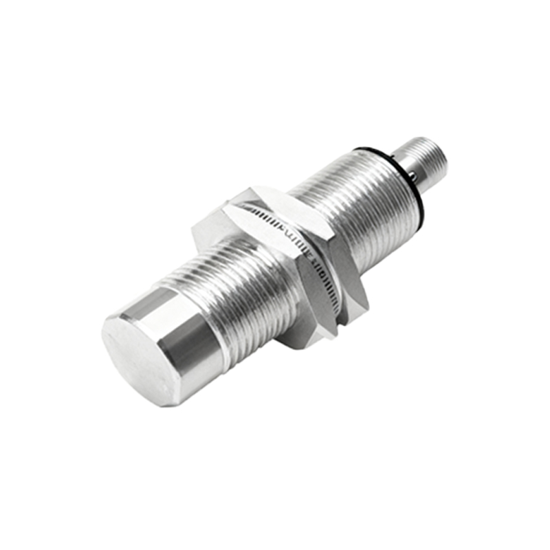
The core of an inductive proximity sensor is a coil wound around a ferrite core, forming an oscillator circuit. This assembly is housed within a sensing face, typically made of a polymer that allows the electromagnetic field to pass through. Behind the oscillator coil, the structure includes a trigger circuit, an amplifier, and an output switching component (like a transistor). A metal housing, often made of nickel-plated brass or stainless steel, encases the entire electronics, providing environmental protection (IP ratings) and electromagnetic shielding. The rear portion contains the connection terminals or an integrated cable. When a metallic object enters the sensor's active electromagnetic field, eddy currents are induced in the target, causing a change in the oscillation amplitude. This change is detected by the trigger circuit, which then signals the output stage to switch states.
Capacitive Proximity Sensor Structure
Structurally similar to inductive types, capacitive proximity sensors have a key difference at the sensing face. They feature two concentric or parallel electrodes acting as the plates of a capacitor, often embedded behind a dielectric material window. The internal oscillator circuit is designed to detect changes in capacitance rather than inductance. The rest of the housing contains the oscillator, signal converter, amplifier, and output stage. This design allows capacitive sensors to detect a wide range of materials, including liquids, powders, plastics, and wood, by sensing the change in the dielectric constant. The housing must carefully isolate the sensing electrodes from the metal casing to prevent interference, often using insulating materials.
Photoelectric Sensor Structure
The structure of a photoelectric proximity switch (diffuse reflective type) is distinctly different. It integrates both a light emitter (typically an LED producing visible red, infrared, or laser light) and a photoelectric receiver (phototransistor or photodiode) within a single housing. The front features a lens system for both the transmitter and receiver. The internal architecture includes the drive circuit for the LED, a highly sensitive amplifier for the receiver signal, and a logic/output circuit. For through-beam types, the emitter and receiver are in two separate housings. The housing is designed to minimize ambient light interference and is often made of coated metal or high-grade plastics with precise optical alignment.
Magnetic (Reed) Proximity Switch Structure
This type has a relatively simple mechanical structure. The core sensing element is a hermetically sealed glass tube (the reed switch) containing two ferromagnetic reeds with contacts. These reeds are overlapped but not touching inside the inert gas-filled tube. This glass capsule is fixed inside a protective plastic or non-magnetic metal housing. When a permanent magnet (the actuator) approaches the sensor, the magnetic field causes the reeds to magnetize, attract each other, and make contact, closing the circuit. The structure is passive for the sensor itself, often requiring an external interface circuit. Its simplicity makes it highly reliable for slow-speed position detection.
Key Structural Components and Materials
Across all types, several structural components are critical. The sensing face material must be chosen for chemical resistance and minimal interference with the sensing field. The housing provides mechanical strength, environmental sealing (IP67/IP69K), and sometimes specific certifications for hazardous areas. Internal PCBAs (Printed Circuit Board Assemblies) host the oscillator, microprocessor, and output circuitry. Potting compounds are often used to encapsulate and protect the electronics from vibration, moisture, and thermal stress. The connection method, whether cable, quick-disconnect (M8/M12 connector), or terminal block, is an integral part of the rear structure, influencing installation ease and strain relief.
Interpreting Structure from Images and Diagrams
Technical datasheets and cutaway diagrams are invaluable for understanding sensor structure. A standard cutaway image typically shows a cross-section view. Engineers should identify: 1) The sensing element location and type (coil, electrodes, optical window). 2) The separation between the sensing element and the housing wall. 3