Introduction to Inductive Proximity Sensors
Inductive proximity sensors are fundamental components in industrial automation, widely used for non-contact detection of metallic objects. These sensors operate on the principle of electromagnetic induction, generating an oscillating electromagnetic field from a coil. When a metallic target enters this field, eddy currents are induced on the target's surface, causing a change in the sensor's oscillation amplitude or frequency. This change is detected and converted into a switching signal. The core of this functionality lies in its electronic circuit, which typically includes an oscillator, a demodulator, a trigger, and an output stage. Understanding the circuit diagram is crucial for engineers to properly select, install, and troubleshoot these sensors in various applications, such as position sensing, counting, or speed monitoring on production lines.
Core Components of the Circuit
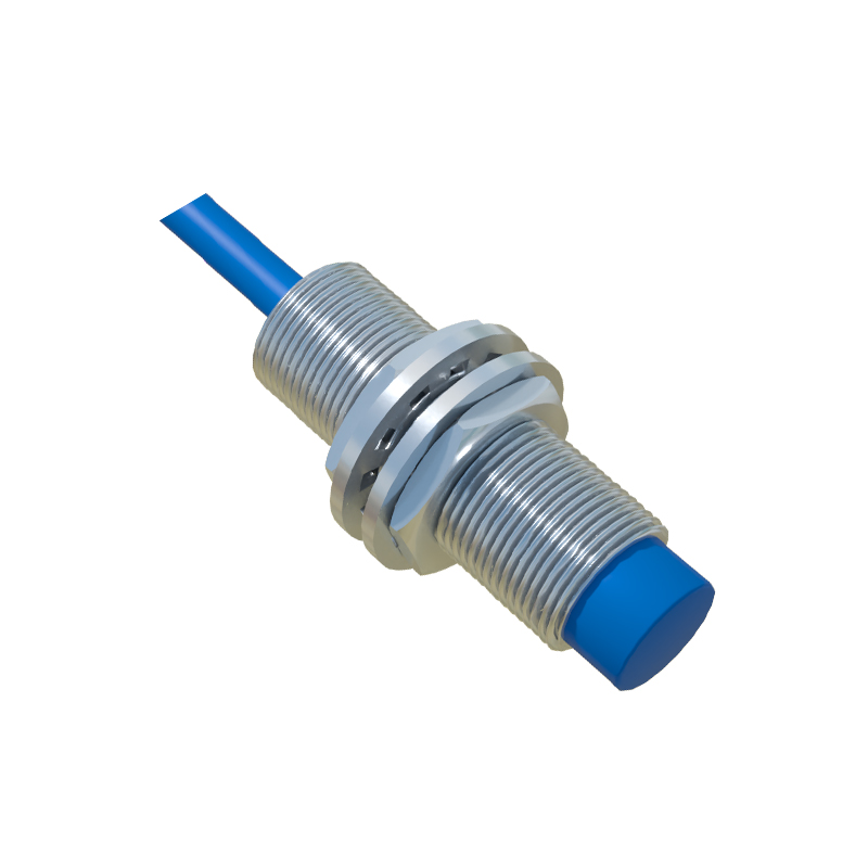
The standard inductive proximity sensor circuit comprises several key sections. The oscillator circuit, often a Colpitts or Hartley oscillator, generates a high-frequency electromagnetic field via the sensor's coil (inductor L). This coil, along with a capacitor (C), forms the resonant tank circuit. The demodulator monitors the oscillation's condition. When a metal object approaches, the energy loss due to eddy currents dampens the oscillation. The demodulator converts this amplitude change into a DC voltage signal. This signal is then fed into a Schmitt trigger or comparator circuit, which provides a clean, hysteresis-based digital output, preventing chatter during state transitions. Finally, the output stage, which can be NPN, PNP, or analog, delivers the switching signal to the control system, such as a PLC.
Detailed Circuit Diagram Analysis
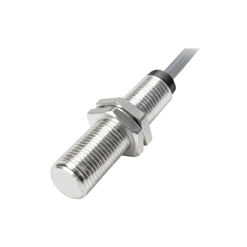
A typical circuit diagram begins with the power supply pins (Vcc and GND). The coil (L1) is connected to the oscillator core, usually involving a transistor (Q1) and feedback capacitors (C1, C2). Resistors (R1, R2) set the bias point for the transistor. The oscillation signal is tapped and sent to the demodulator, often a diode (D1) and filter capacitor (C3) arrangement that rectifies and smoothes the RF signal. The resulting DC level is compared against a reference voltage at the trigger IC (U1). If the level drops below the threshold (indicating target presence), the trigger's output flips. The output transistor (Q2) then switches, connecting the output pin either to ground (for NPN sinking) or to Vcc (for PNP sourcing). Protection components like a series resistor (R3) and a freewheeling diode (D2) are included to safeguard against voltage spikes and reverse polarity.
Design Considerations and Tuning
Designing an effective inductive sensor circuit requires careful consideration. The operating frequency of the oscillator, typically between 100 kHz and 1 MHz, determines the sensor's sensitivity and switching frequency. A higher frequency increases sensitivity to smaller metals but may reduce the sensing range. The coil design (number of turns, core material) directly impacts the electromagnetic field shape and strength. Shielding is another critical factor; shielded sensors have a focused frontal field, while unshielded ones have a larger lateral field. The hysteresis width set in the trigger circuit is vital for stable operation in electrically noisy industrial environments, ensuring the output does not oscillate when the target is at the exact switching point. Temperature compensation circuits are also often integrated to maintain consistent performance.
Common Applications and Integration
These sensors are integrated into myriad systems. In automotive assembly, they detect piston position or gear tooth presence. In packaging machinery, they count metallic items on a conveyor. The circuit's robust NPN/PNP outputs interface directly with programmable logic controllers (PLCs). For analog versions, the circuit is modified to provide a current (4-20 mA) or voltage (0-10V) output proportional to the distance to the target, useful for precision positioning. When integrating, engineers must ensure proper wiring as per the datasheet, considering factors like load current, cable length, and compatibility with the controller's input module. Mounting and environmental conditions (temperature, humidity, contaminants) must also align with the sensor's IP rating.
Troubleshooting Based on Circuit Logic
Understanding the circuit diagram aids significantly in troubleshooting. If a sensor fails to detect a target, one should first verify power (Vcc) at the circuit. Next, using an oscilloscope, check if the oscillator is running by probing the coil terminals. Absence of oscillation could indicate a failed transistor, open coil, or faulty capacitor. If oscillation is present but the output does not switch, the issue may lie in the demodulator or trigger stage—check DC