Understanding Light Curtain Proximity Sensor Components
A light curtain proximity sensor system, crucial for machine safety and object detection, primarily consists of two separate units: the transmitter and the receiver. The transmitter houses an array of synchronized infrared LEDs, while the receiver contains corresponding phototransistors. The system creates an invisible protective screen of light beams. When an object interrupts one or more beams, the receiver's control unit triggers a safety output signal. Before wiring, identify all terminals on both the transmitter and receiver enclosures. Typical terminals include power supply inputs (e.g., 24V DC and 0V), safety output contacts (often OSSD - Output Signal Switching Device, like two PNP or NPN transistor outputs), auxiliary outputs, and possibly muting or blanking function inputs. Always refer to the manufacturer's specific datasheet for the exact pin configuration and electrical characteristics of your model.

Power Supply Connection and Requirements
The first and most critical step is providing a stable and clean power source. Most industrial light curtains operate on a 24V DC supply, though other voltages exist. Connect the positive lead (typically labeled +24V or V+) and the negative lead (0V or COM) from your power supply to the designated terminals on both the receiver and, if required separately, the transmitter. Ensure the power supply is adequately rated for the total current draw of both units. It is highly recommended to use a dedicated, regulated power supply to avoid voltage fluctuations that could cause nuisance tripping or reduced performance. Implement proper fusing or circuit protection as per local electrical codes and the sensor's specifications. Verify polarity carefully; reverse polarity can cause permanent damage to the electronic circuitry.
Wiring the Safety Output Signals (OSSDs)
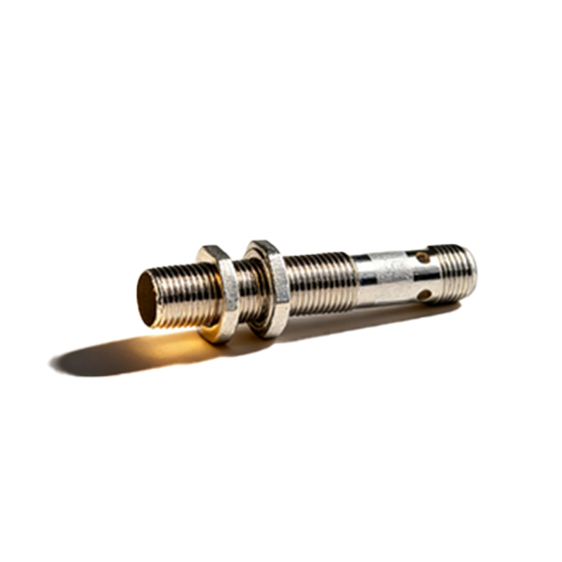
The core safety function is handled by the OSSD outputs. Modern light curtains feature two redundant, complementary signals (OSSD1 and OSSD2) for high reliability. These are typically solid-state PNP (sourcing) or NPN (sinking) outputs. For connection to a safety relay or a safety-rated PLC input, you must understand your controller's input type. For a PNP light curtain output, wire each OSSD signal to a separate input channel on the safety device. The common point of the safety device inputs must be connected to 0V. For an NPN configuration, the common must be connected to +24V. The safety controller monitors both signals. In a normal, unobstructed state, both OSSDs are active (ON). If a beam is broken or a fault is detected, both OSSDs switch off simultaneously, signaling the controller to initiate a safe stop (e.g., remove power from a machine contactor).
Interconnecting Transmitter and Receiver
Synchronization between the transmitter and receiver is essential. This is usually achieved via a dedicated interconnection cable supplied or specified by the manufacturer. This cable carries synchronization signals and often also distributes power from the receiver to the transmitter, simplifying wiring. Never substitute this cable with a standard multi-core cable unless explicitly approved, as it may be specially shielded to prevent electromagnetic interference (EMI) and ensure correct timing. Securely connect this cable between the corresponding sockets or terminals on both units. Ensure the cable is routed away from high-voltage power lines and noise sources to prevent false beam interruptions. The maximum allowable distance between transmitter and receiver is specified in the manual and must not be exceeded.
Connecting Auxiliary Functions and Muting
Advanced light curtain systems offer auxiliary functions. A reset input is common; after an interruption, the beams must be clear, and then a momentary signal applied to the reset terminal to re-enable the OSSD outputs. Muting functions allow temporary, controlled suspension of the protective field for material handling (e.g., allowing a pallet to pass). This requires connecting external muting sensors (like limit switches or photoelectric sensors) to the designated muting input terminals in the correct logic sequence. Blanking functions (fixed or floating) allow specific beams to be ignored, useful for mounting posts or conveyor fixtures. Wiring for these functions is model-specific and must be planned carefully to maintain overall safety integrity. Always follow the safety validation procedures after configuring these features.
Final Testing and Safety Validation
After completing all wiring connections, a thorough inspection and test sequence is mandatory. Visually inspect all terminations for tightness and correct placement. Power on the system and observe the indicator LEDs. Typically, a steady green light on both units indicates normal operation. Systematically test the protective field by interrupting beams with a test rod. Verify that the OSSD signals de-energize immediately and the connected safety