Introduction to Proximity Sensors with Indicator Lights
Proximity sensors with indicator lights, often referred to as "sensing eyes" in industrial automation, are fundamental components in modern control systems. These devices combine the core function of non-contact object detection with a built-in visual status indicator, typically an LED. This integration provides immediate, on-site diagnostic feedback, which is invaluable for machine setup, troubleshooting, and routine maintenance. The indicator light usually illuminates when the sensor detects a target within its specified sensing range, offering a clear, real-time confirmation of the sensor's operational state. This dual functionality enhances system reliability and reduces downtime, making them a preferred choice in applications ranging from packaging and material handling to automotive assembly and robotic guidance.
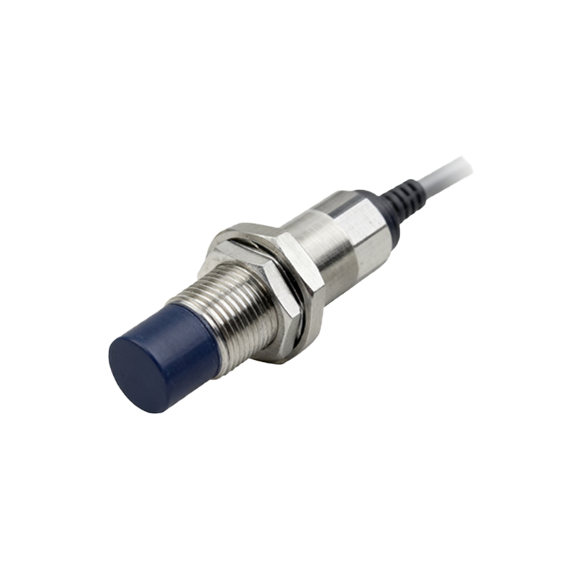
Core Sensing Technologies: Inductive, Capacitive, and Photoelectric
The working principle of the sensor itself is independent of the indicator light but defines its application. The most common types are inductive, capacitive, and photoelectric. Inductive proximity sensors generate an electromagnetic field. When a metallic object enters this field, it induces eddy currents within the target, causing a change in the oscillation amplitude of the sensor's internal LC circuit. This change is detected and converted into a switching signal. Capacitive sensors operate similarly but can detect both metallic and non-metallic materials (like plastic, wood, or liquids) by measuring changes in capacitance caused by the target object altering the electrostatic field. Photoelectric sensors use a light emitter and a receiver; detection occurs when the target interrupts (through-beam) or reflects (retro-reflective or diffuse) the light beam. The indicator light is electrically tied to the output of this sensing circuitry.
Internal Circuitry and Signal Processing
Internally, the sensor comprises several key stages: an oscillator (for inductive/capacitive types) or light source driver (for photoelectric), a signal conditioner, a Schmitt trigger, and an output stage. The oscillator generates a high-frequency field. The signal conditioner amplifies and filters the minute change caused by a target's presence. The Schmitt trigger then converts this analog change into a clean, digital on/off signal, providing hysteresis to prevent output chattering when a target is at the edge of the sensing range. This digital signal directly drives two paths: the solid-state or relay output to the controller (PLC, etc.) and the circuit for the built-in LED indicator. This parallel activation ensures the light provides a true representation of the sensor's electrical output state.
Function and Benefits of the Integrated Indicator Light
The integrated LED serves multiple critical purposes. Primarily, it offers instant visual confirmation of detection, allowing technicians to verify sensor alignment and operation without needing a multimeter or PLC software. During commissioning, one can physically move a target to see the exact point of activation, simplifying adjustment. For troubleshooting, a constantly lit or unlit LED can quickly indicate problems such as a wiring fault, power supply issue, sensor misalignment, or a failed output transistor. Some advanced models feature multi-color LEDs (e.g., green for power, yellow for signal strength, red for detection) or blinking patterns to convey more detailed status information, such as short-circuit warnings or teach-in mode activation.
Wiring Configurations and Output Types
These sensors are available in various wiring configurations, primarily PNP (sourcing) and NPN (sinking), which define how the output signal is provided to the load. The behavior of the indicator light is consistent with the output type. In a 3-wire DC sensor, the LED is connected in parallel to the output switching element. When the sensor detects an object, the output transistor switches, completing the circuit for both the load and the LED, causing it to illuminate. The choice between PNP and NPN must match the input requirements of the connected controller. Additionally, 2-wire AC/DC and analog/IO-Link versions exist, with the indicator light functionality adapted accordingly to reflect the output state or communication status.
Key Selection Parameters and Application Considerations
Selecting the correct sensor involves several parameters beyond the indicator light. The sensing range, influenced by the target material and size, must be sufficient for the application. Repeatability, response frequency, and environmental factors like temperature, humidity, and potential exposure to chemicals or washdowns are critical. The housing material (often nickel-plated brass or stainless steel) and protection rating (IP67/IP69K) ensure durability. The indicator light, while a helpful feature, does not typically affect these core performance specs. However, in environments with high ambient light, a bright LED is essential. Applications are vast, including detecting the presence of a metal part on a conveyor, counting bottles, monitoring fill levels in tanks, or ensuring a robotic