Introduction to Proximity Switch Sensors in Vibratory Systems
Proximity switch sensors are indispensable components in modern industrial automation, particularly within vibratory feeder systems. These non-contact sensors detect the presence or absence of a metallic object—typically a component part being conveyed—without any physical contact. In the context of vibratory feeders, which are used to orient and transport bulk small parts in assembly lines, packaging, and sorting applications, proximity sensors play a critical role in process control, part counting, jam detection, and ensuring consistent feed rates. Their ability to function reliably in environments characterized by constant mechanical vibration, dust, and potential electromagnetic interference is a testament to their robust design and engineering. For electrical engineers designing or maintaining these systems, a deep understanding of sensor selection, installation, and integration is paramount for optimal system performance and minimal downtime.
Core Operating Principles and Technologies
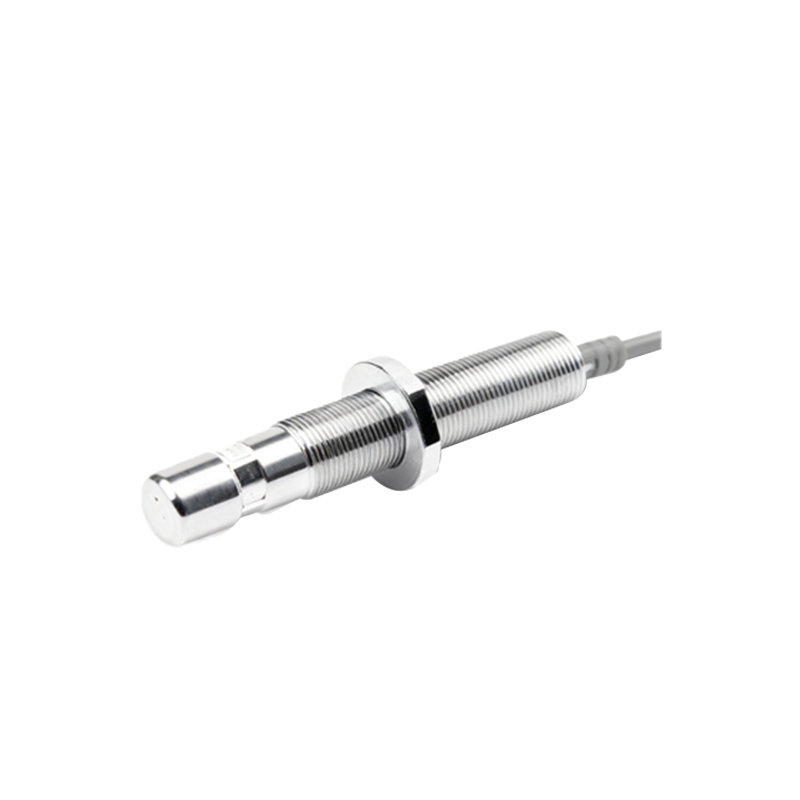
Several sensing technologies are employed in proximity switches for vibratory applications, each with distinct advantages. Inductive proximity sensors are the most common. They generate an electromagnetic field and detect the eddy current losses caused when a metallic target enters this field. These sensors are ideal for detecting ferrous and non-ferrous metals and are highly resistant to contaminants like grease or dust. Capacitive proximity sensors can detect both metallic and non-metallic materials by measuring changes in capacitance. While less common in standard feeder part detection, they can be useful for monitoring non-metallic liners or detecting material build-up. Photoelectric sensors, which use a light beam, are sometimes used but can be susceptible to misalignment from vibration and contamination from dust. The choice of technology hinges on the material of the target part, the required sensing distance, environmental conditions, and the required response speed to keep pace with the feeder's cycle rate.
Key Selection Criteria for Harsh Vibratory Environments
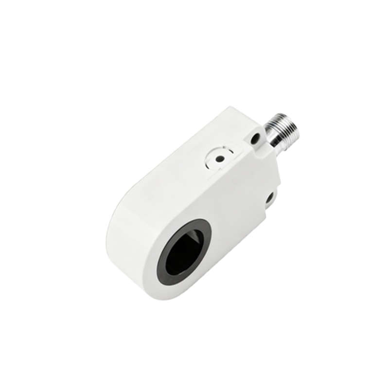
Selecting the right proximity sensor for a vibratory feeder is not a trivial task. The primary enemy is the persistent, high-frequency mechanical vibration. Engineers must prioritize sensors with rugged, all-metal housings (often stainless steel) and high vibration resistance ratings (e.g., 10-30 G). The sensing face should be flush-mountable to prevent physical damage from conveyed parts. The sensing distance, or "snap distance," must be chosen with a safety margin, as vibration can cause momentary variations in the gap between the sensor and the target. Environmental sealing is critical; a rating of IP67 or IP68 is standard, protecting against dust ingress and wash-down procedures. Output type (PNP/NPN, NO/NC) must match the PLC or controller input card. Finally, the switching frequency must exceed the maximum possible part passage frequency to avoid missed counts.
Optimal Installation and Mounting Practices
Proper installation is as crucial as sensor selection. The sensor must be securely mounted to a stable, non-vibrating part of the feeder structure or the base plate, never directly on the vibrating bowl or track. Using locking nuts or other vibration-proof fasteners is essential to prevent loosening. The sensing face should be positioned perpendicular to the target's path of travel, with the gap set to approximately 50-80% of the sensor's rated nominal sensing distance to account for part wobble and vibration-induced movement. Cabling requires special attention: cables should be strain-relieved and routed away from moving parts and high-voltage power lines feeding the feeder's electromagnetic coil to minimize electrical noise. Using shielded cables with proper grounding at the controller end is a best practice for signal integrity.
Integration with Control Systems and Troubleshooting
The sensor's output is typically fed into a Programmable Logic Controller (PLC) or a dedicated feeder controller. The logic programmed uses this signal for critical functions. For example, a sensor placed at the feeder outlet can count parts for batching or trigger a downstream process. A sensor in the track can detect a jam by signaling an absence of parts when the feeder is running. Common integration challenges include false triggering due to vibration (solved by adjusting sensitivity or adding a time delay filter in the PLC logic) and electrical noise from the feeder's AC coil (solved with proper shielding, separation, and sometimes using DC-powered sensors). A systematic troubleshooting approach involves checking power supply, verifying sensor LED indication, measuring output signal with a multimeter, and inspecting for physical damage or misalignment.
Advanced Applications and Future Trends
Beyond basic presence detection, advanced sensor applications are enhancing vibratory feeder intelligence. Analog output sensors can provide continuous distance feedback, allowing for dynamic control of feed rates based on downstream buffer levels. IO-Link enabled smart sensors facilitate digital parameter setting, remote monitoring of operating hours, and predictive maintenance by reporting health status. The integration of multiple sensors along