Understanding the Proximity Sensor Failure
A broken proximity sensor can halt an entire production line, leading to significant downtime and financial loss. These sensors, crucial for detecting the presence or absence of objects without physical contact, can fail due to various reasons. Common failure modes include physical damage from impact or vibration, electrical issues like short circuits or open wiring, environmental factors such as contamination, moisture, or extreme temperatures, and internal component degradation. The first step in any troubleshooting process is to accurately diagnose the failure. Symptoms often manifest as the sensor failing to detect targets, providing inconsistent signals, or not powering on at all. A systematic approach is essential to isolate the root cause and implement an effective repair strategy.
Initial Diagnostic and Safety Procedures
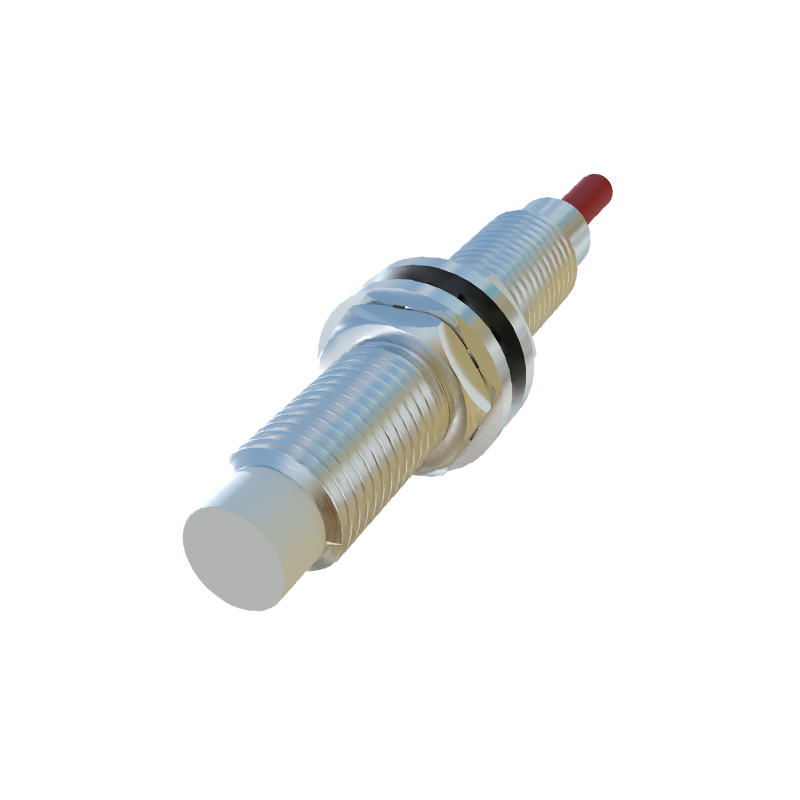
Before touching any components, ensure all safety protocols are followed. De-energize and lock out the electrical circuit supplying power to the sensor and the associated machinery. Confirm zero energy state using a verified multimeter. Once safe, begin with a visual inspection. Look for obvious signs of damage: cracked housing, bent sensing face, severed cables, or corrosion on connectors. Check the mounting bracket for looseness, as vibration can cause misalignment and failure. Examine the environment for excessive dust, oil, or metal chips that could coat the sensing face, impeding its function. Document all observations, as they provide critical clues for the next steps.
Electrical Testing and Signal Verification
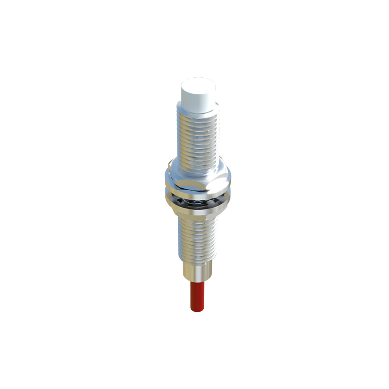
With the sensor disconnected, use a digital multimeter to perform basic electrical checks. First, test the power supply terminals to ensure the correct voltage (e.g., 10-30V DC for many inductive sensors) is present and stable when the circuit is re-energized safely for testing. Next, check the sensor's output. For a 3-wire DC sensor, measure the voltage between the output wire and the negative terminal. Actuate the sensor by bringing a valid target material within its specified sensing range. A PNP (sourcing) sensor should switch from low (near 0V) to high (near supply voltage), while an NPN (sinking) sensor does the opposite. No change indicates a faulty output circuit. Also, check for continuity in the wiring between the sensor and the controller (PLC) to rule out broken wires.
Parameter and Configuration Check
Many modern proximity sensors, especially capacitive or ultrasonic types, have configurable parameters. A sensor might appear "broken" simply because its settings are incorrect. Access the sensor's settings via its teach button or connected software interface. Verify key parameters: sensing distance, output mode (NO/NC), switching hysteresis, and response time. Ensure the sensing distance is appropriately set for the application and that the output logic matches the PLC's expected input. For inductive sensors, confirm the target material is suitable (e.g., ferrous for standard inductive sensors). An incorrect metal or a target that is too small can cause detection failures that mimic a hardware fault.
Component Replacement and Repair Steps
If diagnostics confirm a faulty sensor, replacement is often the most efficient solution. Select an exact replacement model or a fully compatible alternative, matching specifications for type (inductive, capacitive), size, sensing range, output type, voltage, and connection style. During installation, meticulously follow the wiring diagram. For M12 or other quick-disconnect connectors, ensure pins are not bent and the connection is secure and sealed. Proper mounting is critical; ensure the sensor is aligned correctly with the target's path, with no lateral offset. Tighten to the specified torque to avoid damage. After installation, perform a full functional test by cycling the machinery and verifying the sensor's signal triggers the correct machine response at the precise moment.
Preventive Maintenance and Best Practices
To prevent future failures, implement a robust preventive maintenance schedule. Regularly clean the sensor face with appropriate solvents to remove contaminants. Periodically check mounting integrity and cable strain relief. Log environmental conditions and consider upgrading to sensors with higher IP (Ingress Protection) or IK (Impact Protection) ratings if the environment is harsh. Keep a small stock of critical sensor models on hand to minimize downtime. Finally, ensure all maintenance personnel are trained on proper diagnostic procedures. Understanding the operational principles of different sensor technologies—inductive, capacitive, photoelectric, ultrasonic—empowers engineers to troubleshoot more effectively and design more reliable systems from the outset.