Introduction to 3D Proximity Sensing Technology
In the evolving landscape of industrial automation, proximity sensors have become indispensable components for object detection, positioning, and measurement without physical contact. While traditional proximity sensors operate in a single plane, 3D proximity sensors represent a significant technological leap. These advanced devices are capable of detecting an object's presence, distance, and spatial orientation in three-dimensional space. This capability is crucial for complex applications such as robotic guidance, automated assembly, and quality inspection systems. The core principle involves not just determining if an object is 'near,' but precisely quantifying 'how near' and 'where' in a volumetric space relative to the sensor's reference point. This three-dimensional data acquisition enables machines to interact with their environment with unprecedented precision and intelligence, forming the backbone of sophisticated Industry 4.0 and smart factory initiatives.
Core Technologies Enabling 3D Measurement
Several underlying technologies empower proximity sensors to achieve 3D sensing capabilities. The most prevalent include Time-of-Flight (ToF), structured light, and stereoscopic vision. Time-of-Flight sensors work by emitting a light signal, typically from a laser or LED, and measuring the time it takes for the reflection to return. By calculating this round-trip time and knowing the speed of light, the sensor can determine the distance to multiple points on a target object, building a depth map or point cloud. Structured light sensors project a known pattern (like a grid or series of lines) onto an object. A camera then captures the deformation of this pattern upon hitting the object's surface. Sophisticated algorithms analyze this distortion to compute the three-dimensional shape and position. Stereoscopic vision, inspired by human binocular vision, uses two or more cameras placed at a known distance apart to capture images from slightly different angles, enabling depth perception through triangulation.
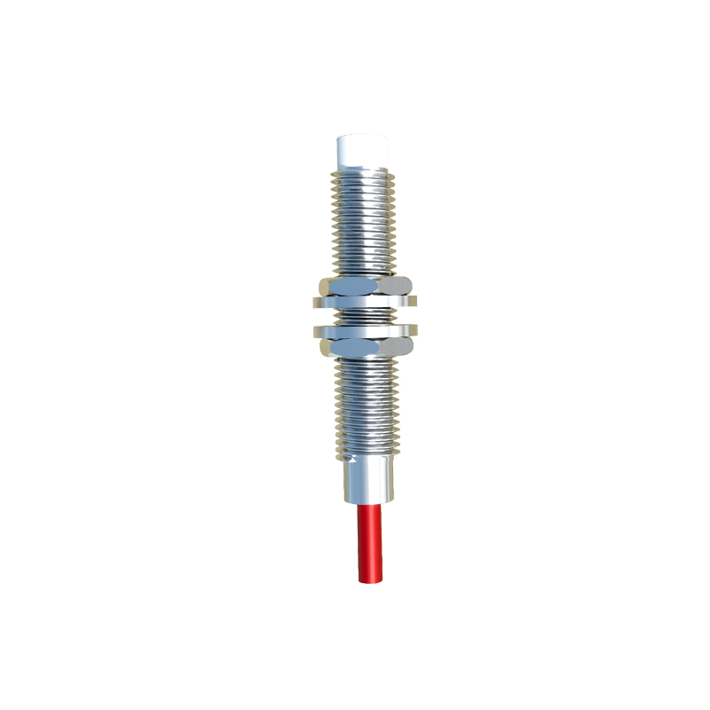
Working Principle: From Emission to 3D Data Point
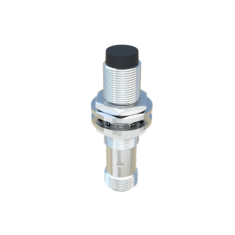
The operational sequence of a 3D proximity sensor is a meticulous process. It begins with the emission phase, where the sensor's transmitter projects energy—be it electromagnetic (light, laser) or ultrasonic waves—into its field of view. This emitted energy interacts with any object within its range. In the reflection and reception phase, a dedicated receiver (a photodiode array, camera, or microphone) captures the modified returning signal. The key differentiator for 3D sensing is the analysis of multiple data points or the entire returned wavefront, not just its amplitude. For instance, a ToF sensor measures the phase shift or direct time delay for millions of points. Finally, in the processing and output phase, an embedded microprocessor or dedicated IC processes the raw signal data. Using complex algorithms, it translates the time delays, pattern distortions, or image disparities into precise X, Y, and Z coordinates for numerous points on the object's surface. This output is often a digital data stream representing a depth map or 3D coordinates.
Key Performance Parameters and Specifications
Evaluating a 3D proximity sensor requires understanding specific parameters beyond standard sensing range. Measurement range defines the minimum and maximum distances within which the sensor can accurately provide 3D data. Field of View (FoV), expressed in degrees horizontally and vertically, determines the volumetric area the sensor can cover. Resolution is critical, indicating the smallest change in position the sensor can detect, often specified separately for lateral (XY) and depth (Z) axes. Accuracy and repeatability define how close the measured values are to the true position and how consistent repeated measurements are, respectively. The measurement speed or frame rate, given in Hertz (Hz), indicates how quickly the sensor can update the 3D data, which is vital for dynamic applications. Finally, environmental ratings for factors like ambient light immunity, temperature, and ingress protection (IP rating) are essential for reliable industrial deployment.
Industrial Applications and Implementation Examples
The practical applications of 3D proximity sensors are vast and transformative. In robotic bin picking, a 3D sensor mounted above a container creates a point cloud of randomly oriented parts, allowing the robot arm to calculate the optimal approach and grip points. For automated assembly, these sensors verify the correct 3D placement and orientation of components before a subsequent operation, such as welding or screwing. In logistics, they are used for volumetric dimensioning of packages on conveyor belts to optimize storage and shipping costs. Quality control systems employ 3D sensors to perform non-contact inspections, detecting surface defects, verifying assembly completeness, or measuring critical dimensions by comparing the captured 3D profile against a CAD model. Furthermore, in autonomous mobile robots (AMRs), 3D proximity sensors, often LiDAR-based, create real-time 3D maps of the environment for navigation and