Understanding Proximity Sensor Fundamentals
Proximity sensors are indispensable components in modern industrial automation, detecting the presence or absence of an object without physical contact. These non-contact sensors operate on various principles, primarily inductive, capacitive, and photoelectric. Inductive sensors detect metallic objects, capacitive sensors detect both metallic and non-metallic materials, and photoelectric sensors use light beams. Before delving into wiring specifics, it is crucial to identify the sensor type (e.g., NPN or PNP, normally open or normally closed) and its operating voltage, typically ranging from 10-30V DC or 90-250V AC. The sensor's datasheet is the primary reference, providing essential details on electrical characteristics, wiring diagrams, and mounting specifications. A clear understanding of these fundamentals ensures correct selection and prevents potential damage during installation.
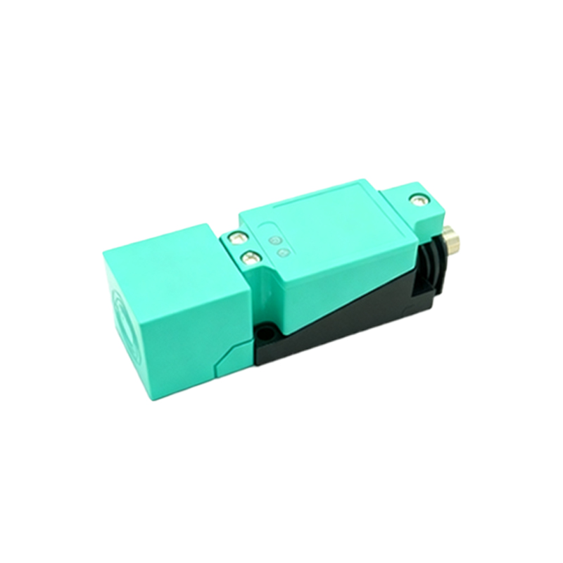
Essential Tools and Safety Precautions
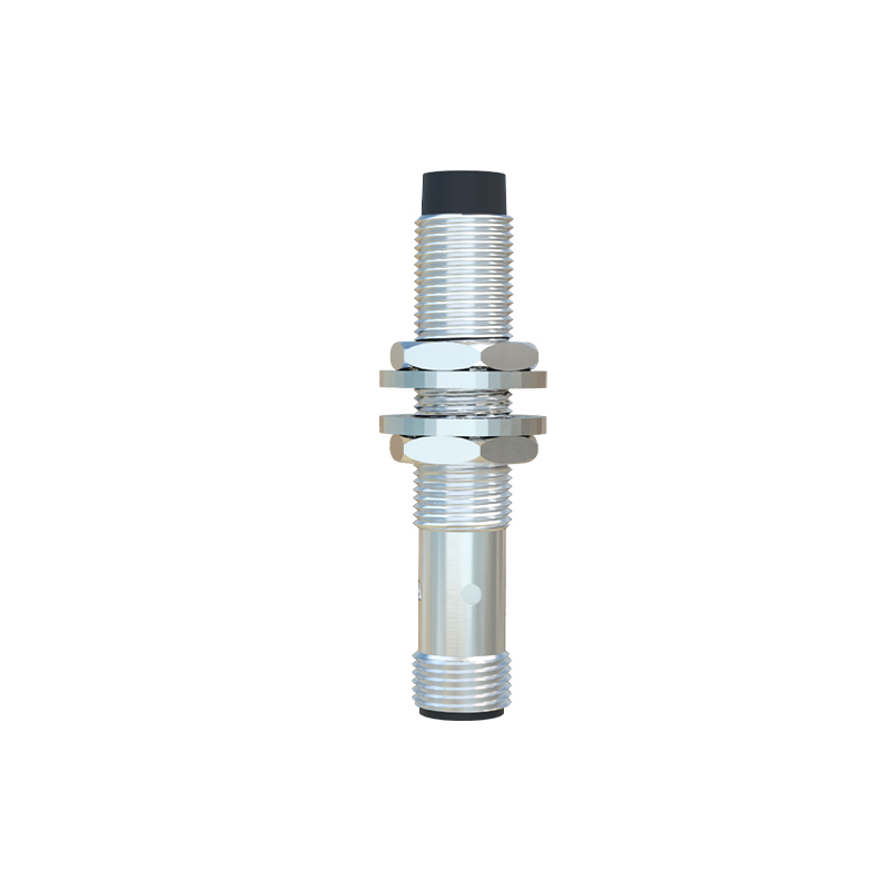
Prior to any wiring task, gathering the appropriate tools and adhering to strict safety protocols is paramount. Essential tools include wire strippers, crimping tools, screwdrivers, a multimeter for continuity and voltage checks, and appropriate gauge wires as specified by the sensor manufacturer. Safety is non-negotiable. Always de-energize the control circuit and lock out/tag out (LOTO) the power source before beginning any wiring work. Verify the absence of voltage using a properly functioning multimeter. Wear appropriate personal protective equipment (PPE) such as insulated gloves and safety glasses. Ensure the work area is clean, dry, and well-lit to avoid accidents and wiring errors.
Wiring DC 3-Wire Proximity Sensors (NPN vs. PNP)
The three-wire DC sensor is the most common configuration in industrial controls. It comprises a brown wire (typically for positive voltage supply, +V), a blue wire (typically for common negative or 0V), and a black wire (the signal output wire). The critical distinction lies in the output type: NPN (sinking) or PNP (sourcing). For a PNP sensor, the brown wire connects to the positive DC supply, the blue wire to the negative DC supply, and the black output wire provides a positive voltage signal to the load (e.g., a PLC input) when activated. The load's other side is connected to the negative supply. Conversely, for an NPN sensor, wiring is similar, but the black output wire sinks current to negative when active. Here, the load is connected between the positive supply and the black wire. Incorrectly mixing NPN and PNP with a controller can lead to malfunction.
Connecting to Programmable Logic Controllers (PLCs)
Integrating proximity sensors with PLCs is a routine task. First, confirm the PLC input module's compatibility (sinking or sourcing). A sourcing input module (seeking a positive signal) pairs with a PNP sensor. A sinking input module (seeking a path to ground) pairs with an NPN sensor. Connect the sensor's brown and blue wires to the DC power supply terminals on the PLC rack or an external power source, ensuring voltage matches. Connect the sensor's black output wire to the designated PLC input terminal (e.g., I0.0). Always use shielded cable for the signal wire, grounding the shield at one end (usually the PLC side) to minimize electromagnetic interference (EMI) which can cause erratic signals.
Wiring 2-Wire AC/DC Proximity Sensors
Two-wire sensors simplify wiring as they connect in series with the load, similar to a mechanical switch. They have only two wires, often brown and blue. These sensors can operate on AC or DC voltage. The key consideration is the "leakage current." Even in the off state, a small current flows through the sensor. This residual current must be lower than the minimum holding current of the connected load (like a relay or PLC input) to prevent the load from remaining activated. A bypass resistor may be required across the load to ensure proper turn-off. Always check the sensor's datasheet for leakage current specifications and the load's minimum current requirements to guarantee reliable switching.
Implementing 4-Wire and Analog Output Sensors
Some advanced proximity sensors feature a four-wire configuration or analog outputs. A four-wire device typically has two separate outputs (e.g., one NPN and one PNP, or two complementary signals) from a single sensing element, offering wiring flexibility for different control schemes. Analog output sensors (e.g., 4-20mA or 0-10V) provide a continuous signal proportional to the sensing distance or target characteristics. Wiring involves connecting the power supply wires (brown/blue)