Understanding Proximity Sensor Fundamentals
Proximity sensors are non-contact devices designed to detect the presence or absence of an object within a defined sensing range. They operate on various principles, primarily inductive, capacitive, ultrasonic, and optical. Inductive sensors generate an electromagnetic field to detect metallic objects, while capacitive sensors respond to changes in capacitance caused by any material. Ultrasonic sensors use sound waves, and optical sensors rely on light beams. The core of their operation involves an oscillator, a sensing coil or surface, a signal conditioner, and an output switch. Interference, whether intentional or as electromagnetic interference (EMI), exploits vulnerabilities in these operational principles. Understanding the specific type—its operating frequency, sensing distance, and output characteristics—is the first critical step in developing an effective interference strategy.
Common Sources of Unintentional Interference
In industrial environments, proximity sensors often face performance degradation from ambient EMI. Common sources include variable frequency drives (VFDs), welding equipment, large motors, and radio transmitters. These can induce noise on the sensor's output lines or directly affect its internal oscillator. For inductive sensors, the presence of non-targeted metals in the sensing field, like metal shavings or nearby machinery, can cause false triggering. For capacitive sensors, changes in humidity, temperature, or the presence of non-target conductive materials can alter the dielectric constant, leading to unreliable operation. Optical sensors are susceptible to ambient light interference, including sunlight or light from other sources hitting the receiver. Identifying these sources is essential for both mitigating unwanted interference and, conversely, for replicating such conditions intentionally.
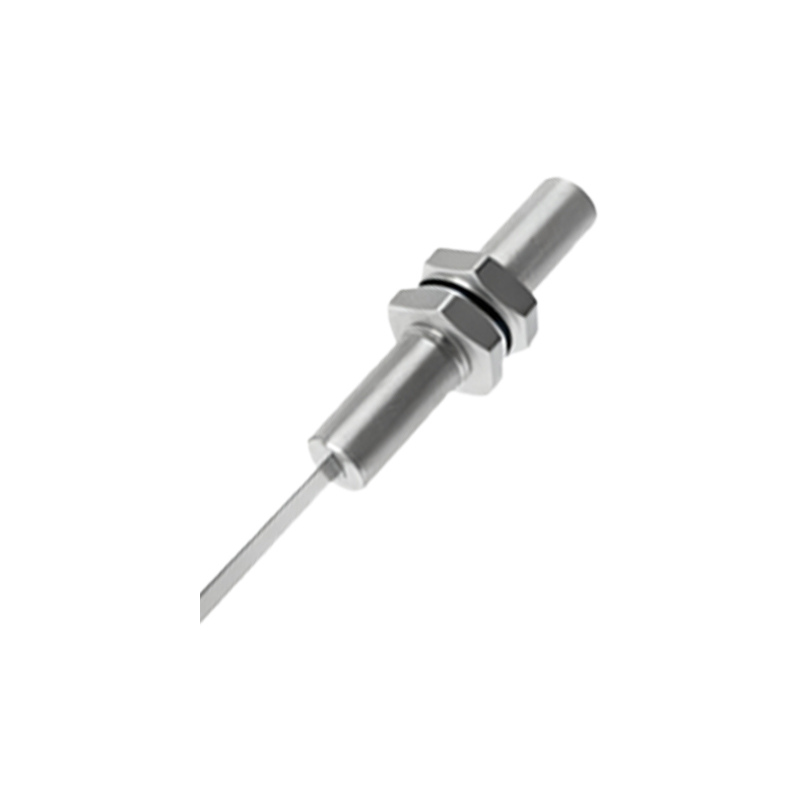
Intentional Interference Methods: Electromagnetic Techniques
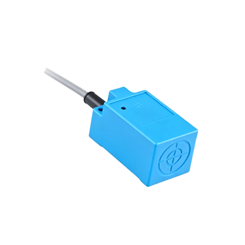
Deliberate interference with inductive proximity sensors often involves manipulating the electromagnetic field. A strong, alternating magnetic field generated near the sensor can saturate its sensing coil, effectively blinding it to its intended target. This can be achieved using a powerful electromagnet or a coil driven by a signal generator tuned to the sensor's resonant frequency—typically in the range of tens of kHz to several MHz. For capacitive sensors, introducing a grounded conductive shield between the sensor and the target can divert the electric field, preventing detection. Alternatively, bringing a large, non-target conductive object into the sensor's field can trigger it falsely. The key is to understand the sensor's operating frequency and field geometry to apply a counter-field of appropriate strength and frequency.
Intentional Interference Methods: Acoustic and Optical Techniques
Ultrasonic sensors can be deceived by generating acoustic noise at their operating frequency. A speaker or another ultrasonic transducer emitting sound waves at the same frequency can create false echoes, causing the sensor to misinterpret distance or detect a non-existent object. For optical sensors, particularly diffuse-reflective types, interference is more straightforward. Directing a light source of a similar wavelength (e.g., an infrared LED for an IR sensor) at the receiver can cause a constant "on" state. For through-beam sensors, blocking the beam is simple, but more sophisticated interference involves modulating a light source to mimic the transmitter's pulse pattern, potentially tricking the receiver. Laser-based sensors require precise alignment for such optical spoofing.
Practical Considerations and Countermeasures
Implementing these interference methods in a real-world scenario requires careful consideration of power, range, and stealth. Generating a strong enough magnetic or acoustic field to affect a sensor from a distance demands significant energy. Furthermore, modern sensors incorporate shielding, frequency hopping, and sophisticated signal processing (like coded light pulses in optical sensors) specifically to reject such interference. Common countermeasures include using shielded cables, proper grounding, installing ferrite cores, employing sensors with DC output, and implementing software-based debounce filters or time-delay functions. Therefore, successful interference often requires detailed reconnaissance of the specific sensor model and its installed environment to identify the weakest link in its design or installation.
Ethical and Legal Implications
It is paramount to address the context of this knowledge. This technical overview is intended for educational purposes, specifically for engineers designing robust systems that must operate in high-EMI environments or for security professionals testing the resilience of critical infrastructure. Knowingly interfering with sensors in industrial automation, security systems, or public infrastructure without explicit authorization is illegal, unethical, and potentially dangerous. It can lead to equipment damage, production downtime, safety hazards, and severe legal consequences. This information should be applied strictly within controlled, legal frameworks such as electromagnetic compatibility (EMC) testing, product development, and authorized penetration testing.