Understanding Proximity Sensor Fundamentals
Proximity switches, or proximity sensors, are non-contact electronic devices designed to detect the presence or absence of an object within their sensing field. They are fundamental components in industrial automation, robotics, and safety systems. Unlike mechanical limit switches, they have no moving parts to wear out, offering high reliability and long service life. The core principle involves generating an electromagnetic field or a beam of light. When a target object enters this field, it causes a change in the sensor's oscillation or light reception, which the internal circuitry converts into a switching signal. The primary types include inductive sensors for detecting metals, capacitive sensors for detecting both metallic and non-metallic materials, and photoelectric sensors using light beams. Understanding this operational basis is crucial before examining the wiring configurations, as the sensor type dictates the compatible power supply and output characteristics.
Key Components and Terminal Designations
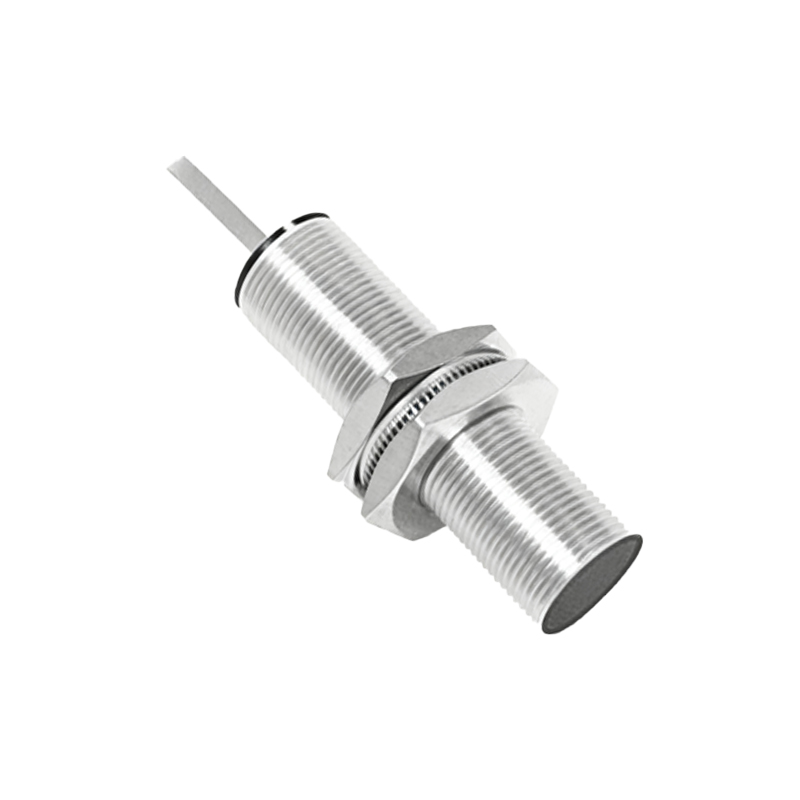
A standard three-wire proximity sensor is the most common configuration in industrial settings. The terminals are typically marked with international standard labels. The brown wire (or terminal marked +V, L+, or 1) is the positive power supply line. The blue wire (or terminal marked 0V, L-, or 2) is the negative power supply or common return line. The black wire (or terminal marked OUT, LOAD, or 3) is the switched output signal line. For two-wire sensors, the two terminals function as both the power supply path and the load switching path, simplifying wiring but with considerations for leakage current. Four-wire sensors often provide both a Normally Open (NO) and a Normally Closed (NC) output from separate wires. It is imperative to consult the specific manufacturer's datasheet for the exact terminal layout, voltage ratings (commonly 10-30V DC or 90-250V AC), and output type (PNP-sourcing or NPN-sinking).
PNP vs. NPN Output Sinking and Sourcing
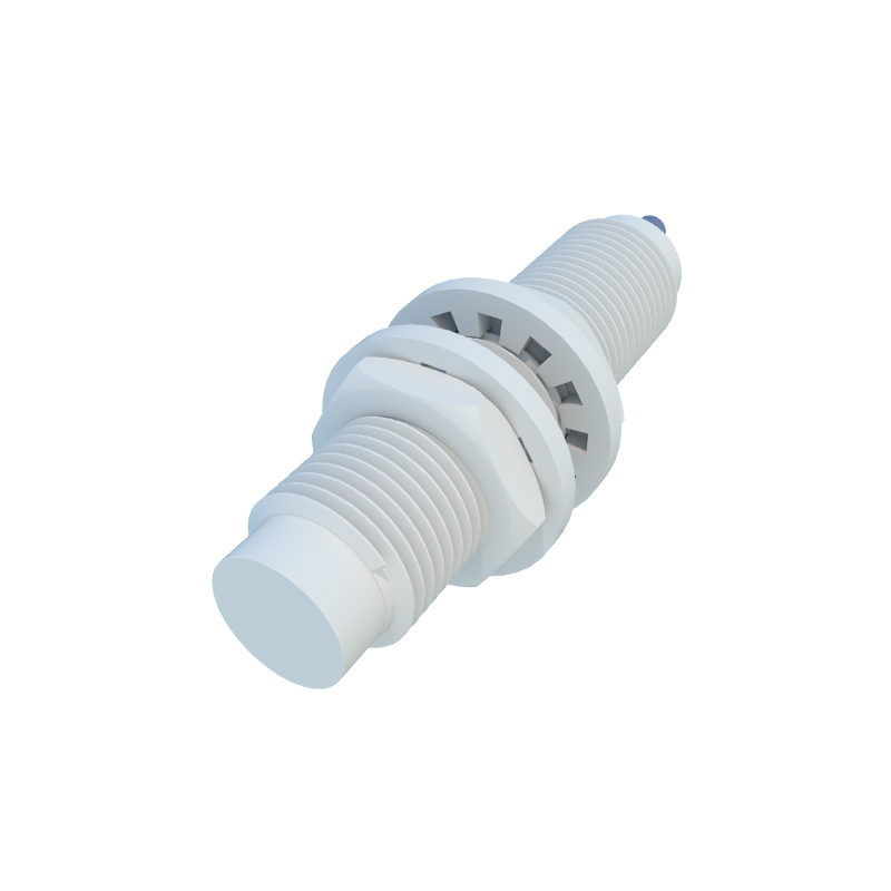
This is a critical distinction in DC sensor wiring. A PNP (Positive-Negative-Positive) sensor, also known as a "sourcing" sensor, switches the positive voltage to the output load. In its active state, the black output wire provides positive voltage to the load, which is then connected to the negative supply (0V). Conversely, an NPN (Negative-Positive-Negative) sensor, or a "sinking" sensor, switches the negative or 0V line. When active, the black output wire connects the load to 0V, while the load is connected to the positive supply. The choice between PNP and NPN often depends on the control system's input card design. PLCs in Europe commonly use PNP inputs, while NPN is traditional in some Asian markets. Mismatching the sensor output type with the controller input can result in a non-functional circuit.
Standard Three-Wire DC Proximity Sensor Wiring Diagram
For a standard three-wire DC inductive proximity sensor with a PNP normally open (NO) output, the wiring procedure is as follows. Connect the brown wire to the positive terminal of a 24V DC power supply. Connect the blue wire to the negative terminal (0V) of the same power supply. The black output wire is connected to one terminal of the load (e.g., a PLC digital input, a relay coil, or an indicator lamp). The other terminal of the load is then connected back to the 0V (blue wire/negative supply) line. When a metal target enters the sensing range, the sensor activates, sourcing 24V DC from the black wire through the load to 0V, completing the circuit and energizing the load. For an NPN sensor, the black wire is connected to the load, and the other side of the load is connected to the positive supply (+24V).
Interfacing with Programmable Logic Controllers (PLCs)
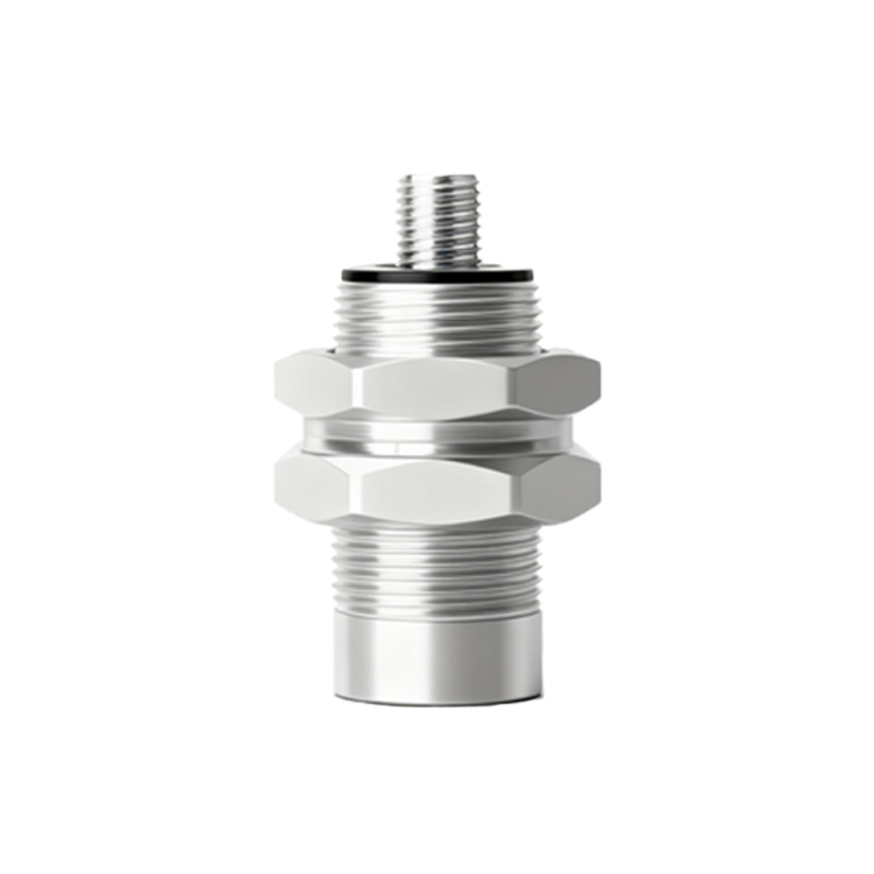
Integrating a proximity sensor with a PLC is a routine application. First, ensure the sensor's voltage rating matches the PLC's sensor supply voltage. For a PNP sensor connected to a PLC sinking input module, wire the sensor's brown wire to +24V DC, the blue wire to the PLC's common 0V, and the black wire directly to the designated PLC input terminal (e.g., I0.0). The PLC input is internally connected to 0V. When the sensor detects an object, it sources current into the PLC input, registering a logic HIGH (1). For an NPN sensor and a PLC sourcing input card, the wiring is reversed: blue to +24V, brown to 0V, and the black wire to the PLC