Introduction to Proximity Limit Sensors
In industrial automation and control systems, proximity limit sensors are indispensable components. They provide non-contact detection of the presence or absence of an object, often serving as critical inputs for machine sequencing, positioning, and safety interlocks. Unlike mechanical limit switches, these sensors operate without physical contact, leading to higher reliability, longer service life, and faster response times. Understanding their schematic diagrams is fundamental for electrical engineers involved in system design, troubleshooting, and maintenance. This article delves into the core principles and typical circuit representations of common proximity sensor types.
Core Operating Principles
The fundamental principle behind a proximity sensor is the disturbance of an electromagnetic field or the emission and reception of a signal. The primary technologies include inductive, capacitive, and photoelectric sensing. Inductive sensors detect metallic objects by generating an oscillating electromagnetic field. When a metal target enters this field, eddy currents are induced, which dampens the oscillation. This change is detected by the sensor's internal circuitry. Capacitive sensors can detect both metallic and non-metallic materials by measuring changes in capacitance caused by the target object altering the sensor's electrostatic field. Photoelectric sensors use a light beam (visible, infrared, or laser) and detect interruptions or reflections of that beam.
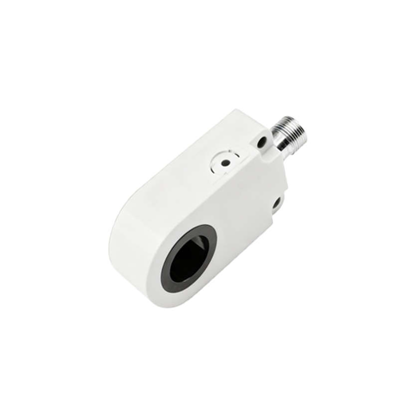
Key Components in a Schematic
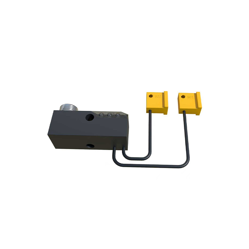
A standard proximity sensor schematic, regardless of type, will depict several key components. First is the sensing element itself, symbolized differently based on technology (e.g., a coil for inductive, plates for capacitive). The oscillator circuit, crucial for inductive and capacitive types, generates the high-frequency field. A trigger circuit monitors the oscillator's amplitude. When the amplitude drops (or rises, depending on design) beyond a set threshold, the trigger activates. This leads to the output stage, which typically features a solid-state switch like a transistor or an IC. The output can be NPN (sinking) or PNP (sourcing). Protection components such as diodes for reverse polarity, resistors for current limiting, and capacitors for noise filtering are also integral parts of the schematic.
Inductive Proximity Sensor Schematic Analysis
Examining a detailed inductive proximity sensor schematic reveals its architecture. The heart is an LC tank circuit (coil and capacitor) forming the oscillator, often a Colpitts or Hartley configuration. This oscillator runs at a high frequency (e.g., 100 kHz to 1 MHz). The coil is the active sensing face. The oscillator's signal is fed into a demodulator and then a Schmitt trigger. When a metal object approaches, the energy loss in the oscillator increases, reducing the amplitude. The Schmitt trigger flips state at a precise threshold, driving the output transistor. A zener diode is commonly shown for voltage regulation, and an LED with a series resistor indicates the output status. The schematic clearly shows the three connections: positive supply (brown/red), negative/ground (blue/black), and the output signal (black/white).
Wiring and Interface with PLCs
The schematic must be understood in the context of the larger control system. For interfacing with a Programmable Logic Controller (PLC), the sensor's output type is critical. An NPN sensor schematic shows the output transistor's collector connected to the load (PLC input) and the emitter to ground. When active, it sinks current from the PLC input to ground, creating a low signal. A PNP sensor schematic shows the emitter connected to the positive supply and the collector to the load; it sources current to the PLC input. The schematic will also indicate the need for a pull-up or pull-down resistor at the PLC input module depending on the sensor type, ensuring a defined logic state when the sensor is off.
Understanding Output Configurations
Schematic symbols differentiate between Normally Open (NO) and Normally Closed (NC) logic outputs. A "normally open" proximity sensor schematic shows a switch symbol (representing the output transistor) that is open when no target is present. When a target is detected, the switch closes, completing the circuit. Conversely, a "normally closed" schematic shows the switch as closed in the idle state, opening upon detection. This is a logical representation; physically, it's always a transistor. Furthermore, schematics for 3-wire sensors explicitly show the separate power and output lines, while 2-wire AC/DC sensor schematics depict the device in series with the load, functioning as a switch that also passes the operating current.
Common Schematic Symbols and Markings
Standardized symbols are used in schematics for clarity. The sensor housing is often shown as a rectangle or circle. The sensing face is indicated by parallel lines or a special icon (