Introduction to 6-Wire Proximity Sensors
Proximity sensors are fundamental components in industrial automation, providing non-contact detection of metallic or other objects. While 3-wire and 4-wire configurations are common, the 6-wire proximity sensor offers enhanced functionality and diagnostic capabilities. This design typically integrates a standard switching output with additional, independent diagnostic or complementary outputs. Understanding the wiring diagram for these sensors is crucial for proper installation, troubleshooting, and leveraging their full potential in complex control systems. The six wires usually correspond to power supply, ground, a primary output (often NPN or PNP), a complementary secondary output, and sometimes dedicated wires for diagnostic feedback like a short-circuit signal or an operating state indicator.
Decoding the Standard Wire Color Coding
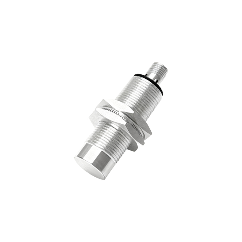
Although manufacturers may vary, a common color standard exists for 6-wire DC sensors. Typically, the Brown wire is connected to the positive DC supply voltage (+V). The Blue wire is universally designated for the DC common or 0V (ground). The Black wire is frequently the primary output signal wire (NO - Normally Open). The White wire often serves as the complementary output, which could be Normally Closed (NC) or a second independent channel. Two additional wires, commonly Gray and Pink, are used for diagnostic functions. The Gray wire might be for a short-circuit output or a diagnostic pulse, while the Pink wire could indicate a sensor malfunction or "diagnosis enable" function. It is imperative to always consult the specific sensor's datasheet, as deviations from this scheme are possible.
Detailed Circuit Diagram and Connections
The core circuit involves connecting Brown (+V) and Blue (0V) to a stable DC power source, typically 10-30V DC. The load for the primary output (e.g., a PLC input, relay coil) is connected between the Black wire and the positive supply or ground, depending on the sensor's sinking (NPN) or sourcing (PNP) configuration. For a sourcing (PNP) sensor, the Black wire switches the positive voltage to the load, which is then connected to Blue/0V. The White wire's complementary output is wired similarly to an independent load. The diagnostic wires (Gray, Pink) are connected to separate monitoring inputs on a controller. For instance, the Gray diagnostic output might go low in case of a wire break or overload, providing a pre-failure warning. A simplified internal circuit block diagram shows a sensing oscillator, signal conditioner, two independent output switches (often solid-state), and a diagnostic monitoring circuit all powered from the two supply lines.
Wiring Configurations: Sourcing (PNP) vs. Sinking (NPN)
The 6-wire sensor's primary output channel (Black wire) adheres to standard PNP or NPN logic. In a PNP (sourcing) configuration, the Black wire acts as a switched positive source. When an object is detected, the internal switch closes, connecting the Black wire to the internal +V (Brown), sourcing current to the load connected to 0V. In an NPN (sinking) configuration, the Black wire acts as a switched ground. Upon detection, it connects to the internal 0V (Blue), sinking current from a load connected to +V. The complementary output (White wire) usually follows the same logic type as the primary output. The diagnostic outputs are typically open-collector NPN types regardless of the main output configuration, requiring a pull-up resistor to the supply voltage for proper operation when connected to a monitoring device.
Application Scenarios and System Integration
The dual-output feature of a 6-wire sensor is highly valuable. It can control two separate circuits simultaneously—for example, one output triggering a machine cycle while the other activates a pilot light. More advanced uses involve safety monitoring by wiring the complementary outputs in a cross-check circuit to detect internal sensor faults. The dedicated diagnostic wires enable predictive maintenance. By connecting the Gray diagnostic output to a PLC, the system can log intermittent faults or receive an early warning of impending sensor failure before the main output stops functioning, minimizing unplanned downtime. This makes 6-wire sensors ideal for critical applications in automotive manufacturing, packaging machinery, and complex material handling systems where reliability and diagnostics are paramount.
Troubleshooting Common Wiring Issues
Incorrect wiring is a frequent source of malfunction. A constant off condition on the main output may indicate reversed power supply polarity (Brown/Blue swapped) or a load connected to the wrong polarity relative