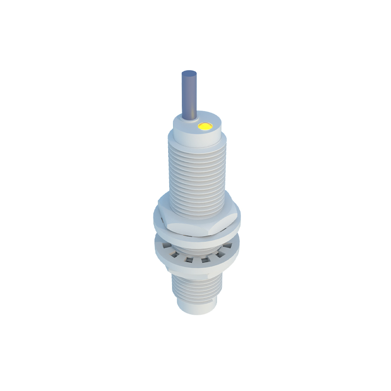
Introduction to Proximity Sensor Malfunction
A proximity sensor switch that remains in a permanently "on" state represents a critical and disruptive failure mode in industrial automation systems. These non-contact devices, designed to detect the presence or absence of a target object without physical contact, are fundamental to countless processes, from assembly line sequencing to safety interlocking. When a sensor fails to switch off, it can cause machinery to operate incorrectly, halt production lines, or create hazardous conditions. This persistent activation, often indicated by a continuously illuminated LED on the sensor body, signals that the sensor is continuously detecting a target, even when none is present. Understanding the root causes of this failure is essential for maintenance personnel and engineers to ensure system reliability, minimize downtime, and maintain operational safety. The issue transcends simple nuisance alarms, pointing to deeper electrical, environmental, or mechanical problems within the sensing loop.
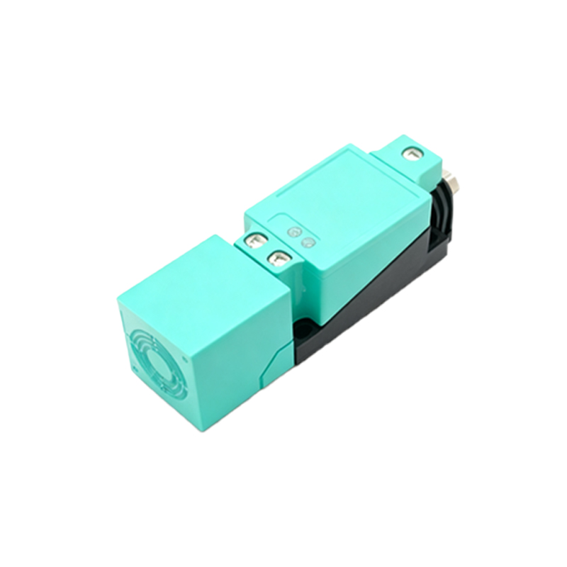
Primary Causes of Continuous Activation
Several factors can lead to a proximity sensor remaining in a latched "on" state. The most common cause is sensor overload or damage. Excessive voltage spikes, often from inductive loads like solenoids or motors without proper suppression, can damage the internal solid-state switching components, causing them to short-circuit and remain closed. Physical damage to the sensing face or housing from impact or vibration can also disrupt internal circuitry. Another frequent culprit is environmental contamination. Metallic dust, chips, or conductive fluids accumulating on the sensor face can create a false "target," effectively tricking the sensor into constant detection. For inductive sensors, the presence of a different, unintended ferrous or non-ferrous metal in the sensing field can have the same effect. Electrical issues, such as a short circuit in the wiring between the sensor output and the controller input (PLC), will also present as a sensor staying on, as the control system receives a constant signal.
Sensor Type-Specific Considerations
The troubleshooting approach must consider the specific technology of the proximity switch. Inductive sensors, which detect metallic objects, can be affected by the installation environment. If mounted too close to another metal surface (like the machine frame), it may sense that as a permanent target—a condition known as "side sensing" or "shielding effect." Reducing the mounting distance or using a shielded (flush-mountable) sensor type can resolve this. Capacitive sensors, which detect a wider range of materials including liquids and plastics, are particularly susceptible to environmental changes. Fluctuations in humidity, temperature, or the buildup of non-conductive material on the sensing face can alter the dielectric constant and cause false triggering. Ultrasonic and photoelectric sensors can be fooled by background reflections, acoustic noise, or ambient light interference, leading to a constant output signal. Checking and adjusting sensitivity thresholds and ensuring a clean, unobstructed sensing path are crucial first steps for these types.
Systematic Diagnostic Procedure
A logical, step-by-step diagnostic process is key to efficiently resolving the issue. First, perform a visual inspection of the sensor, its mounting, and the surrounding area. Look for physical damage, contamination, moisture, or the presence of any unintended object within the nominal sensing range. Next, isolate the sensor from the system. Disconnect the sensor's output wires from the PLC or load. Using a multimeter, measure the output signal directly at the sensor terminals. If a DC sensor, measure voltage; for a current-sinking (NPN) sensor, the output should switch between a high impedance (off) and near 0V (on) relative to the negative supply. If the output remains low (on) even with no target present, the sensor is confirmed faulty. If the output behaves correctly when disconnected, the fault lies in the wiring or the load/PLC input module, possibly due to a short circuit or a damaged input channel.Electrical and Load Verification
Verifying the electrical supply and load compatibility is a critical step. Ensure the power supply voltage to the sensor is within its specified range. Both under-voltage and over-voltage conditions can cause erratic behavior. Check for proper grounding and shield connections, as electrical noise from variable frequency drives (VFDs) or welding equipment can induce false signals. Examine the load connected to the sensor's output. The sensor's maximum switching current and leakage current specifications are vital. If the load impedance is too high (e.g., a PLC input with a very high input resistance), the sensor's inherent leakage current—a small current that flows even when the output is "off"—may be sufficient to keep the PLC input activated. This is a common issue. The solution is to add a "bleeder" or "load" resistor in