Understanding Proximity Sensor Wiring Fundamentals
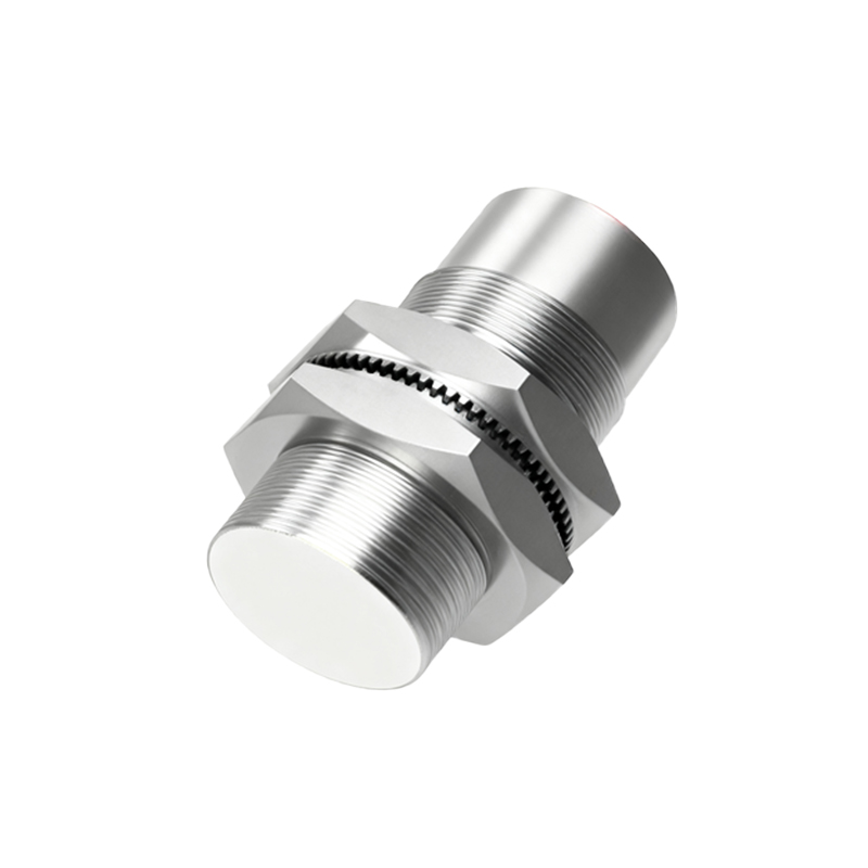
Proximity sensors are essential components in industrial automation, detecting the presence or absence of an object without physical contact. Correct wiring is critical for reliable operation and system safety. These sensors typically fall into two main categories based on their output configuration: 2-wire, 3-wire, and sometimes 4-wire sensors. The 2-wire sensor acts like a switch in series with the power supply, simplifying installation but requiring careful consideration of leakage current. The 3-wire sensor, the most common type, has separate power, ground, and signal wires, offering more stable performance. Understanding the sensor's datasheet—specifying whether it is NPN (sinking) or PNP (sourcing)—is the first and most crucial step before any physical connection is made. Incorrect wiring can lead to sensor failure, erratic machine behavior, or even damage to the programmable logic controller (PLC) input module.
Essential Tools and Safety Precautions
Before beginning the wiring process, gather the necessary tools: appropriate wire strippers, crimping tools, screwdrivers, a multimeter for continuity and voltage checks, and the sensor's technical documentation. Safety is paramount. Always ensure the control circuit power is completely locked out and tagged out (LOTO) before handling any wires. Verify that the voltage rating of the sensor (commonly 10-30V DC or 90-250V AC) matches your power supply. Wear appropriate personal protective equipment (PPE). Identify the wiring diagram, usually found on the sensor body or its datasheet, which clearly labels the terminals (e.g., Brown wire for +V, Blue for 0V/Common, Black for output signal, and White for a second output or function).
Wiring a 3-Wire DC Proximity Sensor
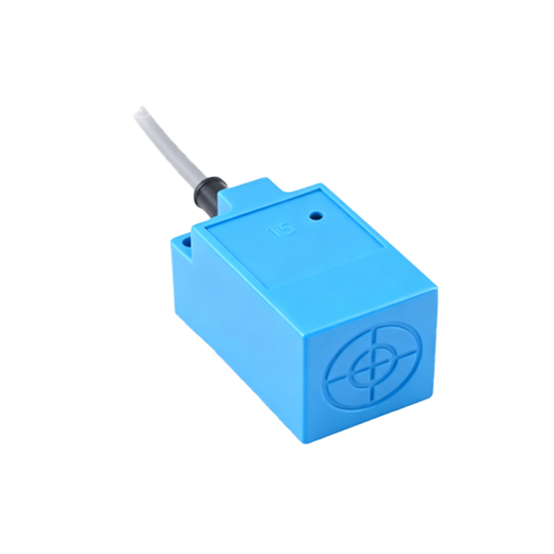
The 3-wire DC sensor is the industry standard. For a PNP (sourcing) sensor, connect the brown wire to the positive DC supply voltage (+V). Connect the blue wire to the DC common or negative (0V). The black wire is the switched output; when the sensor detects a target, it will source current from the +V supply to this wire. This black output wire is then connected to the input terminal of your PLC or relay. For an NPN (sinking) sensor, the wiring is similar, but the function is reversed: the brown wire still connects to +V, and the blue to 0V. However, the black output wire will sink current to 0V when activated. Therefore, the PLC input must be wired to receive a sinking signal, often requiring a common-positive configuration. Always use shielded cable for longer runs to prevent electrical noise interference, grounding the shield at the controller end only.
Connecting to a PLC Input Module
Integrating the sensor with a PLC requires matching the sensor's output type with the PLC input card's specifications. For a PNP sensor connected to a sinking PLC input, the PLC common for that input group is typically connected to 0V. The sensor's black output wire connects to the specific PLC input point. When the sensor activates, it provides a positive voltage signal to the input. For an NPN sensor connected to a sourcing PLC input, the PLC common is connected to +V. The sensor's black wire connects to the input point, pulling it low to 0V upon detection. It is a common and serious error to connect an NPN sensor output directly to a sinking PLC input without a pull-up resistor, which may result in a "floating" input and unreliable readings. Consult both the sensor and PLC manuals for definitive wiring schematics.
Wiring 2-Wire AC/DC Sensors and 4-Wire Models
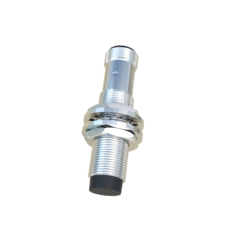
Two-wire sensors are wired in series with the load and the power supply, similar to a mechanical switch. They are polarity-insensitive for AC models but require correct polarity for DC versions. A key consideration is the "leakage current" when the sensor is off; this residual current must be lower than the holding current of the connected relay or PLC input to prevent false activation. A bleeder resistor may be necessary. Four-wire sensors typically provide two complementary outputs (e.g., one NPN and one PNP, or a normally-open and normally-closed pair). They offer greater flexibility for control logic. The fourth wire, often white, provides the second output signal. The wiring follows the same principles: identify the power wires (brown/blue), then connect the output wires (black/white) to their respective destinations based on the required logic.