Understanding the Core Function of Proximity Sensors
Proximity sensors are fundamental components in modern industrial automation, providing non-contact detection of metallic or, in some cases, non-metallic objects. Their primary function is to convert the presence or absence of a target into an electrical signal, which is then used by a Programmable Logic Controller (PLC) or other control systems to trigger actions. Common types include inductive sensors for metals, capacitive sensors for various materials, and ultrasonic sensors for distance measurement. When a sensor becomes non-responsive, it halts or disrupts the automated process, leading to downtime, potential safety hazards, and production losses. A systematic approach to diagnosing the issue is therefore critical for maintenance personnel and engineers.
Initial Visual and Operational Checks
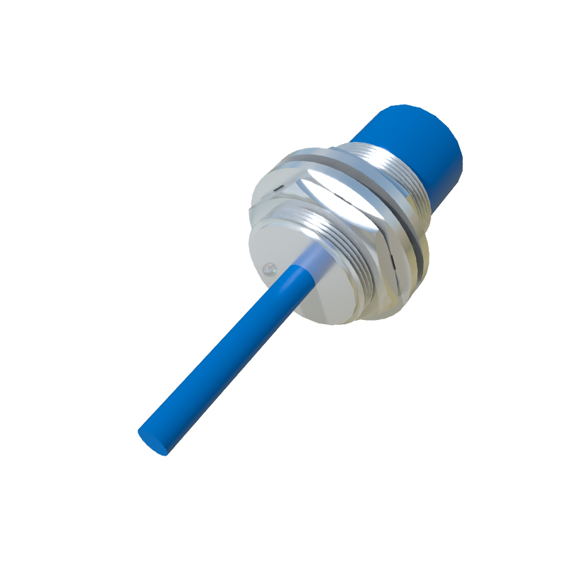
Before delving into complex diagnostics, always perform a basic visual and operational inspection. First, ensure that the target object is within the sensor's specified sensing range and is of the correct material and size. Check for any physical damage to the sensor housing, cable, or connector. Look for accumulated debris, dust, metal shavings, or coolant fluid on the sensing face, as contamination is a frequent cause of failure. Verify that the indicator LED (if present) is behaving as expected. A solid or blinking light might indicate a specific error state as per the manufacturer's manual. Manually trigger the sensor with a known good target to see if the output changes.
Verifying Power Supply and Wiring Integrity
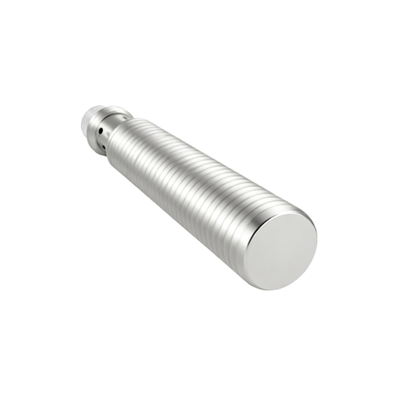
A significant percentage of sensor failures stem from electrical issues. Begin by confirming that the power supply voltage matches the sensor's specifications (e.g., 10-30V DC). Use a multimeter to measure the voltage directly at the sensor's terminals while connected to the circuit. Low voltage can cause unreliable operation. Next, inspect the wiring connections for looseness, corrosion, or broken wires. Pay close attention to the cable gland entry point, a common failure area due to stress. Ensure the wiring follows the correct diagram: typically, brown wire to positive (+V), blue wire to negative (0V/COM), and black wire as the output signal. For a sinking (NPN) sensor, the black wire should connect to the load, which is then connected to positive. For a sourcing (PNP) sensor, the black wire connects directly to the positive side of the load.
Diagnosing Output Signal and Load Issues
If power is confirmed, the next step is to check the output signal. Disconnect the sensor's output wire from the PLC or load. Connect your multimeter in voltage mode between the sensor's output wire (black) and the common (blue). When a target is presented, the voltage should switch. For a PNP sensor, it should go from near 0V to near the supply voltage. For an NPN sensor, it should go from high to low. If the signal switches correctly at the sensor but not at the PLC input, the issue lies in the wiring between them or the PLC input module itself. Also, verify that the load (e.g., PLC input, relay coil) is within the sensor's maximum current rating. An overloaded sensor can fail or behave erratically.
Environmental Factors and Sensor Configuration
Industrial environments are harsh. Electrical noise from variable frequency drives (VFDs), welding equipment, or large motors can interfere with sensor operation. Ensure sensor cables are routed away from power cables and are properly shielded. Grounding the shield at one end is crucial. Consider the operating temperature; extreme heat or cold can affect performance. For capacitive sensors, changes in humidity or the presence of different materials nearby can alter the sensing characteristics, requiring re-calibration. Additionally, check if the sensor has any configuration switches (e.g., for output mode NO/NC, short-circuit protection, or response time) and ensure they are set correctly for the application.
Advanced Diagnostics and Final Steps
If all previous steps yield no results, more advanced diagnostics are needed. Use an oscilloscope to examine the quality of the output signal for noise or instability. Try substituting the suspect sensor with a known working unit of the same model. If the new sensor works, the original is likely faulty. However, if the problem persists, the issue may be systemic, such as a failing power supply or a ground loop. Consult the sensor's datasheet for specific error codes or diagnostic procedures. Finally, consider the possibility of mechanical misalignment or vibration loosening the sensor mount over time. Once the root cause is identified and corrected, document the failure and solution for future reference, aiding in predictive maintenance strategies.