Introduction to PLC and Proximity Sensors
Programmable Logic Controllers (PLCs) are industrial digital computers adapted for controlling manufacturing processes, such as assembly lines or robotic devices. Proximity sensors, on the other hand, are non-contact sensors that detect the presence or absence of objects within their sensing range. When combined, PLCs and proximity sensors form a critical component in automation systems, enabling precise control and monitoring. The integration involves a schematic diagram that outlines the electrical connections and logic flow, ensuring reliable operation in various industrial applications. This article delves into the schematic principles, detailing how PLCs interface with proximity sensors to achieve efficient automation.
Basic Working Principle of Proximity Sensors
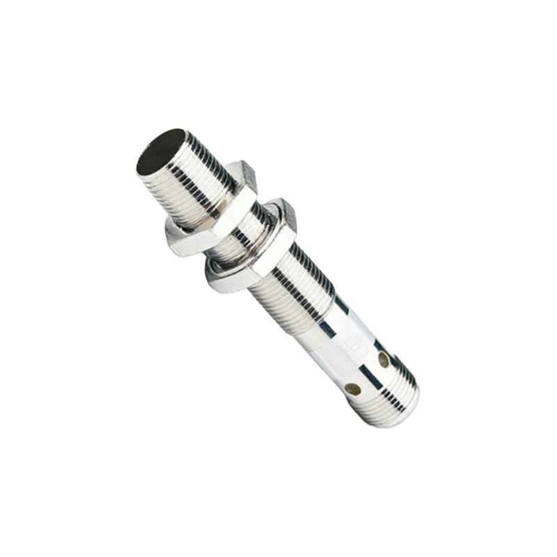
Proximity sensors operate based on electromagnetic, capacitive, or inductive principles, depending on the type. Inductive proximity sensors, for instance, generate an electromagnetic field and detect changes caused by metallic objects. When an object enters the sensing zone, it alters the field, triggering an output signal. This signal is typically a digital switch, such as a PNP or NPN transistor output, which can be connected to a PLC input module. Understanding this principle is essential for designing a schematic, as it dictates the sensor's wiring and compatibility with the PLC system. The output signal must match the PLC's input specifications to ensure proper communication and control.
Components of a PLC Control Schematic
A typical PLC control schematic for proximity sensors includes several key components. First, the proximity sensor itself, with its power supply connections (usually 12-24V DC) and output wires. Second, the PLC input module, which receives the sensor signal and processes it according to the programmed logic. Third, wiring diagrams show how to connect the sensor to the PLC, often involving terminal blocks, cables, and grounding points. Additionally, protective devices like fuses or surge suppressors may be included to safeguard against electrical faults. The schematic serves as a blueprint, guiding engineers in installation and troubleshooting, and must adhere to industry standards for safety and performance.
Wiring and Connection Details
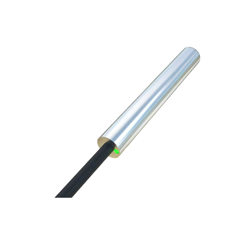
Wiring a proximity sensor to a PLC involves careful attention to polarity and voltage levels. For a standard three-wire DC sensor, the connections include a positive supply wire (brown), a negative or ground wire (blue), and an output wire (black). The output wire is linked to a specific input terminal on the PLC input module. In the schematic, these connections are depicted with clear labels and symbols, such as IEC or ANSI standards. It's crucial to ensure that the PLC's common terminal matches the sensor's output type (sourcing or sinking). Proper wiring minimizes interference and false triggers, enhancing system reliability. Diagrams often include notes on cable routing and shielding to prevent noise from affecting signal integrity.
PLC Programming for Sensor Integration
Once the hardware is connected via the schematic, PLC programming comes into play. The program, written in ladder logic or other PLC languages, defines how the PLC responds to sensor inputs. For example, when a proximity sensor detects an object, it sends a signal to the PLC, which can then activate an output, such as turning on a motor or triggering an alarm. The schematic may reference program addresses or tags, linking physical connections to logical functions. Programming considerations include debounce timers to filter noise, edge detection for precise timing, and error handling for fault conditions. This integration ensures that the sensor data is used effectively for control tasks.
Common Applications and Benefits
PLC-controlled proximity sensors are widely used in industries like automotive, packaging, and material handling. Applications include object detection on conveyor belts, position sensing in robotic arms, and safety interlocks in machinery. The schematic diagram facilitates easy maintenance and scalability, allowing engineers to modify or expand systems without extensive rewiring. Benefits include improved accuracy, reduced downtime, and enhanced safety, as proximity sensors provide non-contact sensing that avoids wear and tear. By following a well-designed schematic, companies can achieve cost-effective automation with high reliability and compliance to regulatory standards.
Troubleshooting and Best Practices
Troubleshooting a PLC and proximity sensor system often starts with the schematic diagram. Common issues include wiring errors, power supply problems, or sensor misalignment. The schematic helps identify test points, such as voltage levels at PLC inputs or sensor outputs. Best practices involve regular calibration of sensors, using shielded cables to reduce electromagnetic interference, and documenting any changes to the schematic for future reference. Additionally, simulating the PLC program before deployment can prevent logic errors. By adhering to these practices, engineers ensure long-term performance and minimize operational disruptions in industrial environments.
Conclusion and Future Trends
In summary, a