Introduction to Infrared Proximity Sensing
Infrared proximity sensors are fundamental components in modern automation, robotics, and consumer electronics. These devices operate by emitting an infrared light beam and detecting its reflection from a nearby object. The core functionality hinges on interpreting the sensor's output signal, which conveys critical distance or presence information. Unlike simple on/off switches, the output can vary in form—analog voltage, digital pulses, or serial data—depending on the sensor's design and application requirements. Understanding these signals is paramount for engineers integrating sensors into systems for object detection, collision avoidance, or level sensing. This article delves into the characteristics, types, and processing of output signals from typical IR proximity sensors.
Analog Voltage Output Signals
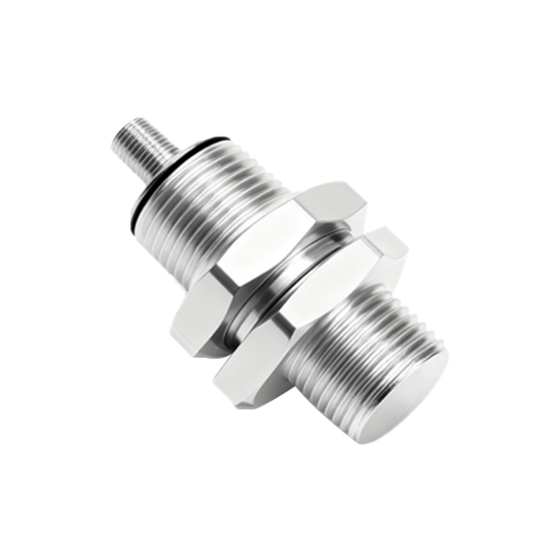
A common output type is an analog voltage signal. Typically, the output voltage is inversely proportional to the distance between the sensor and the target object. For instance, a sensor might output 5V when no object is detected (infinite distance) and a decreasing voltage as an object approaches within its sensing range, perhaps dropping to 0.5V at the minimum detectable distance. This linear or non-linear relationship is detailed in the sensor's datasheet. This analog signal requires an Analog-to-Digital Converter (ADC) in a microcontroller for interpretation. Engineers must consider factors like output impedance, noise immunity, and required filtering circuits to ensure signal integrity, especially in electrically noisy industrial environments.
Digital and Switch-Type Outputs
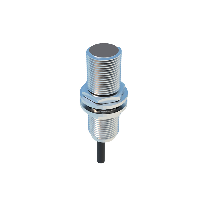
Many IR proximity sensors provide a simple digital output, acting as a proximity switch. These often incorporate an internal comparator circuit. When the received infrared signal strength (corresponding to object proximity) crosses a predefined threshold, the output toggles from a logic HIGH to LOW state, or vice versa. This threshold is sometimes adjustable via a potentiometer on the sensor module. Digital outputs are straightforward to interface with microcontrollers or PLCs, requiring only a digital input pin. They are ideal for applications like counting objects on a conveyor belt, detecting the open/closed state of a door, or triggering an alarm when an intrusion is detected within a specific range.
Modulated and PWM Output Signals
To enhance immunity to ambient infrared light interference (e.g., from sunlight or incandescent lamps), many sophisticated IR sensors use a modulated infrared beam. The corresponding output signal often reflects this modulation. One prevalent form is a Pulse Width Modulation (PWM) signal. The duty cycle of the PWM wave may vary with distance. Alternatively, the sensor might output a digital pulse train where the frequency or pulse width correlates to the measured proximity. Processing these signals involves using a microcontroller's input capture or timer peripherals to measure pulse timing accurately, allowing for higher precision and stability compared to basic analog readings.
Serial Communication Protocols (I2C, UART)
Advanced IR proximity sensor modules, particularly those with integrated digital signal processing, often communicate via standard serial protocols like I2C (Inter-Integrated Circuit) or UART (Universal Asynchronous Receiver-Transmitter). Instead of a raw voltage or pulse, these sensors output formatted data packets containing calculated distance values, often in millimeters or centimeters, and sometimes additional status flags. This abstracts the complexity of signal conditioning from the system designer. The host processor simply reads a register over I2C or receives a data string over UART. This method simplifies wiring, supports daisy-chaining multiple sensors on a bus, and provides robust, noise-resistant communication.
Signal Conditioning and Processing
Raw output signals frequently require conditioning for reliable use. For analog signals, this may involve operational amplifier circuits for scaling and offset adjustment, followed by low-pass filtering to suppress high-frequency noise. Digital signals may need debouncing circuits or software algorithms to eliminate contact chatter. For PWM or serial data, proper timing and protocol configuration in firmware are essential. Additionally, environmental factors like the object's reflectivity, color, and surface texture significantly affect the signal strength. Therefore, calibration routines and adaptive thresholding in software are often necessary to ensure consistent performance across different operating conditions and target materials.
Integration and Application Considerations
Selecting the correct output type is an application-driven decision. Simple presence detection in a vending machine might only need a digital switch output. In contrast, a robotic arm requiring precise positioning would benefit from an analog or high-resolution serial-output sensor. Integration involves ensuring voltage level compatibility (e.g., 3.3V vs. 5V logic), providing a stable power supply with adequate decoupling capacitors, and implementing appropriate electrical isolation if the sensor operates in a different ground domain. Proper mechanical mounting to avoid crosstalk between the emitter and receiver, and shielding from direct ambient IR sources, are