Understanding Proximity Sensor Failure
Proximity sensors are fundamental components in modern industrial automation, providing non-contact detection of metallic or non-metallic objects. When a proximity sensor fails, it can lead to unexpected machine downtime, production errors, and potential safety hazards. A faulty sensor typically manifests through symptoms like intermittent operation, complete lack of response, or erratic signal output. The root causes are diverse, ranging from environmental factors like excessive vibration, temperature extremes, and contaminant buildup to electrical issues such as voltage spikes, wiring faults, or internal component degradation. Recognizing these early signs is the first critical step in effective troubleshooting.
Initial Diagnostic Procedures
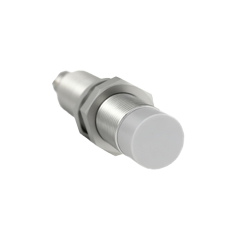
Before concluding the sensor itself is defective, a systematic diagnostic approach is essential. Begin by performing a visual inspection. Check for obvious physical damage, corrosion on the housing, or loose connections at the sensor head and cable entry. Ensure the sensing face is clean and free from metal chips, grease, or other debris that could interfere with its operation. Next, verify the power supply. Using a multimeter, confirm that the sensor is receiving the correct voltage within its specified range, typically 10-30V DC for most industrial models. Inspect the wiring for shorts, breaks, or poor connections in the conduit.
Testing Sensor Output and Functionality
With power confirmed, the next step is to test the sensor's output. For a 3-wire DC sensor, connect your multimeter between the output wire (usually black or blue) and the negative terminal. Actuate the sensor by bringing the specified target material within its sensing range. Observe the voltage change. A PNP (sourcing) sensor should switch from near 0V to near supply voltage when activated. An NPN (sinking) sensor will do the opposite. No change indicates a problem. For a 2-wire AC/DC sensor, measure the voltage drop across the sensor; it should decrease significantly when activated. Also, listen for the internal relay click in AC models, though not all sensors have audible feedback.
Analyzing Load and Environmental Factors
A common misdiagnosis occurs when the load connected to the sensor is the actual culprit. Check the load's current draw against the sensor's maximum switching capacity. An overloaded sensor can fail prematurely or behave erratically. Furthermore, reassess the installation environment. Radio Frequency Interference (RFI) from nearby motors or welders can disrupt solid-state sensors. Ensure proper grounding and shielding. Verify the sensing distance; remember that the rated sensing distance is for a standard target. Different materials or smaller targets reduce effective range. Sensor misalignment or target approach from the wrong angle can also cause perceived failure.
Internal Component Failure and Repair Considerations
If power, wiring, load, and environment are ruled out, internal failure is likely. The oscillator circuit, which generates the electromagnetic field, can fail. The output switching transistor or triac is another common point of failure, especially after electrical transients. While some technicians attempt component-level repair on expensive sensors, it is generally not recommended for standard units. The sealed housing is often difficult to open without damage, and the repair may not restore the original environmental protection rating (IP rating). In most industrial settings, replacement with a new or certified repaired unit is the most reliable and cost-effective solution.
Preventive Maintenance and Best Practices
Preventing proximity sensor failure is more efficient than repairing it. Implement a regular maintenance schedule that includes cleaning sensor faces, checking mounting integrity, and verifying electrical connections. Use surge protection devices on supply lines in areas prone to voltage spikes. Select the correct sensor type for the application—consider factors like sensing distance, target material, housing material (e.g., stainless steel for washdown areas), and output configuration. Ensure proper installation by following the manufacturer's guidelines for mounting, cable bending radius, and use of conduit. Keeping a log of sensor failures can help identify recurring issues in specific machine locations or processes.
Selecting a Replacement Sensor
When replacement is necessary, do not simply order an identical part number without review. Use the failure as an opportunity to re-evaluate the application. Consider upgrading to a more robust model with a higher IP rating, wider voltage range, or short-circuit protection. Verify the electrical characteristics (PNP/NPN, NO/NC) and physical dimensions, including thread size and connector type, to ensure compatibility. For critical applications, having spare sensors in stock is a best practice to minimize downtime. Always source sensors from reputable distributors or directly from the manufacturer to guarantee quality and authenticity.
SEO