Understanding Proximity Sensor Function and Failure Signs
Proximity sensors are critical components in automated industrial systems, detecting the presence or absence of an object without physical contact. Common types include inductive, capacitive, and photoelectric sensors. A failing sensor often exhibits clear symptoms: erratic machine behavior, such as unintended stops or skipped cycles; inconsistent detection, where objects are sometimes missed; complete loss of signal output; or visible physical damage like cracks or corrosion. Before concluding the sensor is faulty, perform basic diagnostics. Verify the power supply voltage matches the sensor's specifications using a multimeter. Check the wiring for loose connections, fraying, or short circuits. Ensure the target object is within the sensor's specified sensing range and is made of an appropriate material. Sometimes, environmental factors like excessive dust, coolant splash, or strong electromagnetic interference can mimic sensor failure.
Preparing for the Replacement Procedure
Safety is the paramount concern. Always follow lockout/tagout (LOTO) procedures to isolate the machine from all energy sources—electrical, pneumatic, and hydraulic. Gather the necessary tools: appropriate wrenches or screwdrivers, a multimeter, wire strippers, and terminal crimpers. Obtain the correct replacement sensor. Match the exact model number or ensure technical compatibility: verify the sensing type (e.g., inductive for metals), sensing distance, output type (PNP/NPN, NO/NC), voltage rating, housing size, and connection style (pre-wired cable or quick-disconnect). Having the machine's electrical schematic diagram is invaluable for identifying wire functions. Document the existing setup by taking photos of the sensor's wiring and mounting position.
Step-by-Step Sensor Removal Process
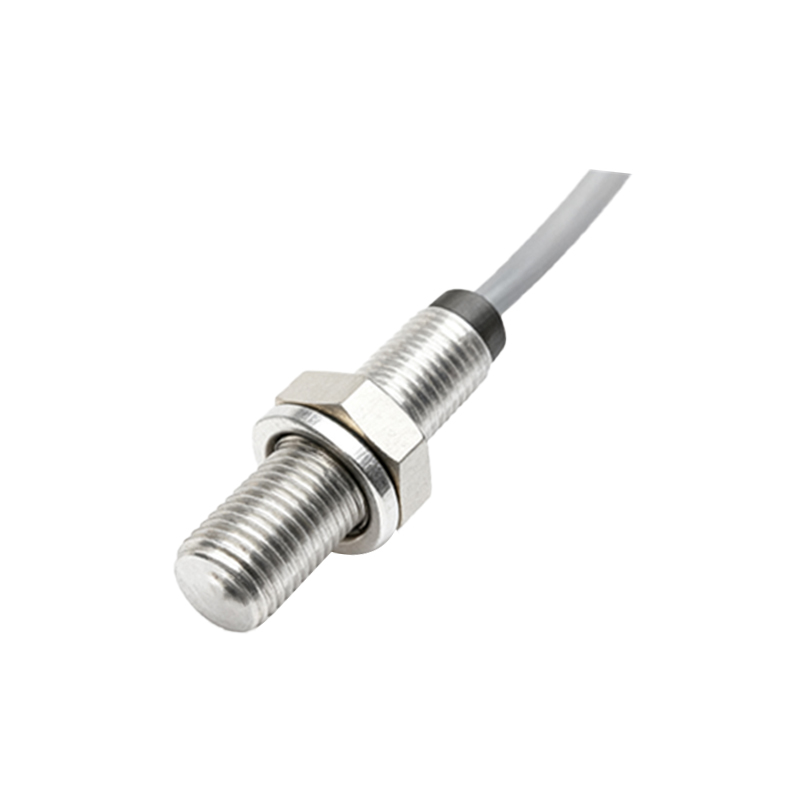
Begin by disconnecting the sensor from its power source. For sensors with quick-disconnect plugs, simply unplug them. For hard-wired units, you must access the electrical cabinet. After confirming zero energy with a voltage tester, carefully label each wire connected to the sensor's terminals according to your documentation or standard color codes (e.g., brown for +V, blue for 0V, black for output). Use a small piece of tape and a marker for this. Once labeled, disconnect the wires. Next, remove the sensor from its mounting bracket. This usually involves loosening one or two locking nuts. Note any washers or shims used for alignment. Gently extract the sensor from its housing. Inspect the mounting area for debris or damage and clean it if necessary.
Installing and Mounting the New Sensor
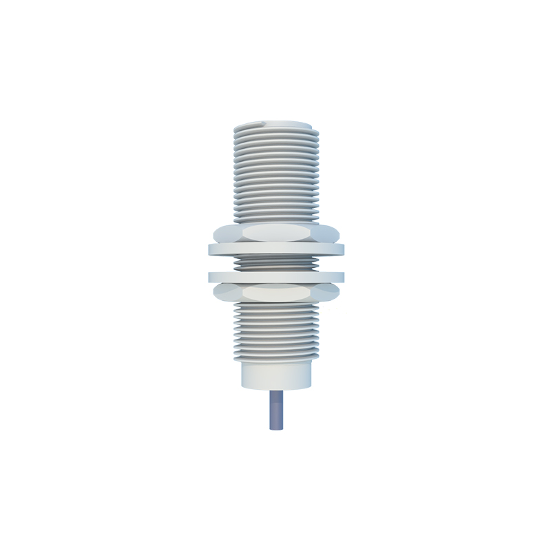
Take the new proximity sensor and, if applicable, attach any provided mounting hardware or brackets. Insert the sensor into the mounting location. Do not fully tighten the locking nut yet. Precise alignment is crucial for reliable operation. For cylindrical sensors, ensure it is perpendicular to the target's path. Use the manufacturer's recommended gap tool or a feeler gauge to set the correct distance between the sensor's face and the target object. The target should pass consistently within this sensing range. For threaded barrel sensors, you may need to adjust the depth. Once properly positioned and aligned, securely tighten the mounting nut to the specified torque, if available, to prevent vibration from loosening it.
Electrical Connection and Wiring Verification
Proceed to connect the wires to the new sensor's terminals. Refer to your labels and the sensor's datasheet. Typically, connect the positive supply wire (often brown) to the +V terminal, the negative/ground wire (often blue) to the 0V terminal, and the output signal wire (often black) to the output terminal. Ensure connections are tight and secure. Use ferrules on stranded wires for best reliability in terminal blocks. If the sensor has a quick-disconnect plug, simply mate it with the corresponding socket. Before restoring power, double-check all connections against the schematic. Visually inspect for any loose strands or potential shorts. Ensure the sensor's body is not contacting any metal surfaces that could cause grounding issues.
Configuration, Testing, and Commissioning
Most standard proximity sensors are pre-configured and require no adjustment. However, some models feature sensitivity potentiometers or teach-in functions. Consult the manual if configuration is needed. After a final visual inspection, restore power to the machine circuit. Observe the sensor's indicator LED (if equipped). It should illuminate steadily when power is applied and may blink or change state when a target is detected. Perform a functional test. Manually cycle the target object past the sensor several times. Use your multimeter in voltage mode to confirm the output signal switches correctly between high and low states as expected. Finally, integrate the sensor back into the machine's operational cycle. Run