Introduction to Inductive Proximity Sensors
Inductive proximity sensors are non-contact electronic devices designed to detect metallic objects within their sensing range. Operating on the principle of electromagnetic induction, these sensors generate an oscillating electromagnetic field from a coil wound around a ferrite core. When a metallic target enters this field, eddy currents are induced in the target, causing a change in the oscillation amplitude or frequency of the sensor's internal LC tank circuit. This alteration is detected and converted into a switching signal, typically through a Schmitt trigger or comparator circuit, enabling reliable object detection without physical contact. Widely used in industrial automation, these sensors offer high durability, resistance to environmental contaminants like dust and moisture, and precise detection capabilities for various metals, including steel, aluminum, and copper. Their robustness makes them ideal for harsh manufacturing environments, such as assembly lines, robotics, and machinery safety systems.
Core Circuit Components and Operation
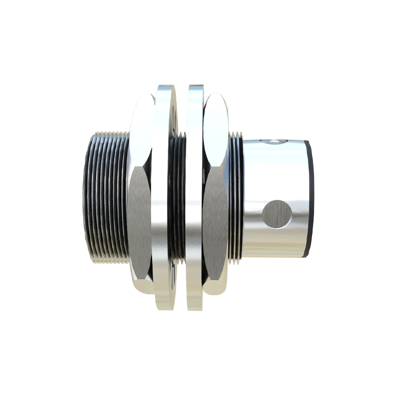
The fundamental circuit of an inductive proximity sensor comprises several key components that work in harmony to achieve detection. At its heart is an LC oscillator, where an inductor (the sensing coil) and a capacitor form a resonant tank circuit, generating a high-frequency electromagnetic field. This oscillator is driven by an amplifier, often based on a transistor or integrated circuit, to maintain stable oscillations. A demodulator circuit monitors the oscillation amplitude; when a metal object approaches, the induced eddy currents dampen the oscillations, reducing the amplitude. This change is fed into a threshold detector, such as a Schmitt trigger, which compares the signal to a predefined level and produces a clean digital output—either ON or OFF. Additional components may include a voltage regulator to ensure stable power supply, output drivers (like open-collector transistors or solid-state relays) for interfacing with controllers, and protection circuits against overvoltage or short circuits. The entire system is typically housed in a shielded metal or polymer casing to minimize external interference and enhance sensitivity.
Design Considerations for Optimal Performance
Designing an effective inductive proximity sensor circuit requires careful attention to multiple factors to ensure reliability and accuracy. First, the coil design is critical: the number of turns, wire gauge, and core material influence the sensing range and frequency, with higher frequencies (often 100 kHz to 1 MHz) allowing for better detection of non-ferrous metals. Shielding the coil can reduce unwanted detection of surrounding metals, improving target specificity. Circuit stability is another priority; temperature compensation techniques, such as using temperature-stable capacitors or feedback loops, help maintain consistent performance across varying environmental conditions. Power consumption must be optimized, especially for battery-operated applications, by selecting low-power components and implementing sleep modes. Noise immunity is enhanced through filtering circuits and proper grounding, preventing false triggers from electromagnetic interference in industrial settings. Finally, the output configuration—whether NPN or PNP, normally open or closed—should match the control system requirements, ensuring seamless integration with PLCs or microcontrollers.
Applications in Industrial Automation
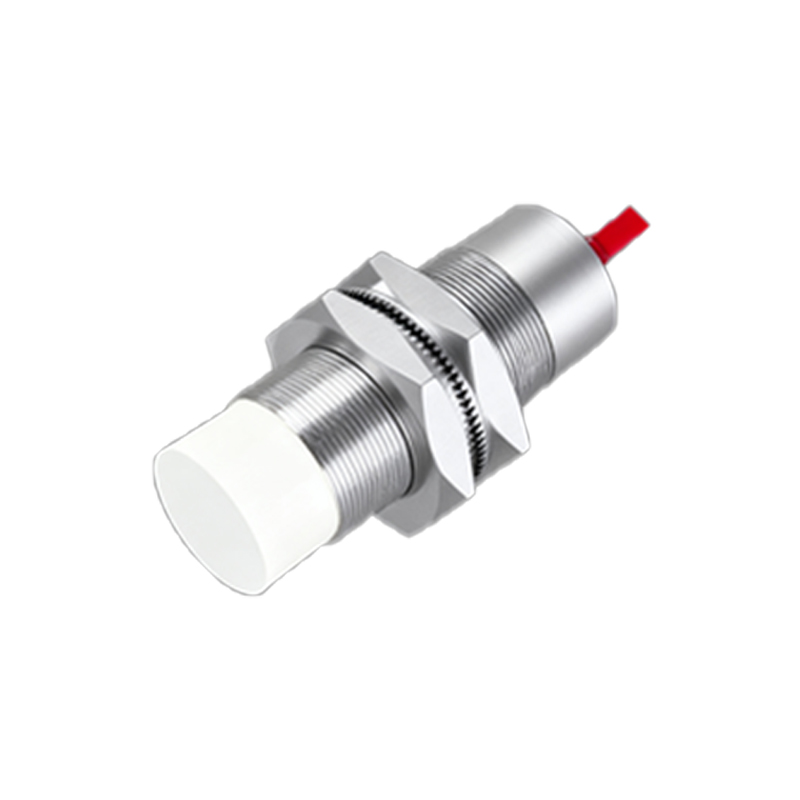
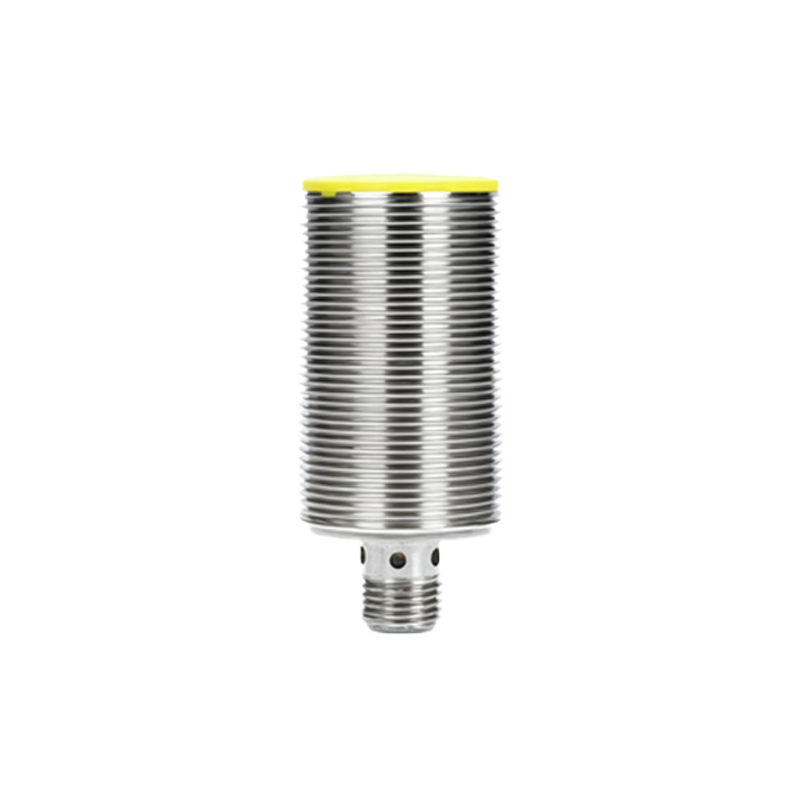
Inductive proximity sensors play a vital role in modern industrial automation, offering versatile solutions for object detection and positioning. In manufacturing lines, they are used to count parts, monitor conveyor belt movements, and verify the presence of components in assembly processes. Robotics relies on these sensors for end-effector positioning and collision avoidance, enabling precise movements in automated welding or painting systems. Safety applications include detecting door closures in machinery guards or monitoring hazardous zones to prevent accidents. Additionally, they facilitate quality control by identifying metal defects or verifying material types in sorting systems. Their ability to operate in tough conditions—such as high temperatures, vibration, or exposure to oils—makes them indispensable in automotive, packaging, and metalworking industries. With advancements in miniaturization and smart sensing, newer models integrate diagnostics and communication protocols like IO-Link, providing real-time data for predictive maintenance and Industry 4.0 initiatives.
Common Challenges and Troubleshooting Tips
Despite their robustness, inductive proximity sensors can face issues that affect performance. One common challenge is reduced sensing range due to buildup of debris or misalignment with targets; regular cleaning and proper installation according to manufacturer guidelines can mitigate this. Electrical interference from nearby motors or power lines may cause erratic switching, which can be addressed by using shielded cables, separating sensor wiring from high-voltage lines, and adding ferrite beads. Temperature extremes might drift the sensor's response, so selecting models with wide operating temperature ranges or implementing thermal compensation is advisable. If a sensor fails to detect objects, check the power supply voltage, output load compatibility, and ensure the target material is within the specified detectable metals. For false triggers, verify the mounting environment—avoid placing sensors near other metal surfaces or adjusting the sensitivity threshold if adjustable. Routine maintenance, including testing with known metal samples,