Understanding Proximity Switch Fundamentals
Proximity switches, also known as proximity sensors, are non-contact electronic devices designed to detect the presence or absence of an object within their sensing field. Unlike mechanical limit switches, they operate without physical contact, leading to significantly longer service life and higher reliability in harsh industrial environments. The core principle involves generating an electromagnetic field or a beam of light. When a target object enters this field, it causes a change in the sensor's oscillation amplitude, capacitance, or light reception. This change is processed by the internal circuitry, which subsequently triggers a switching action in the output stage. Common types include inductive (for detecting metals), capacitive (for detecting both metals and non-metals like liquids or plastics), and photoelectric sensors. Selecting the correct type is the foundational step before any wiring commences, as it dictates the electrical characteristics and connection requirements.
Key Wiring Components and Specifications
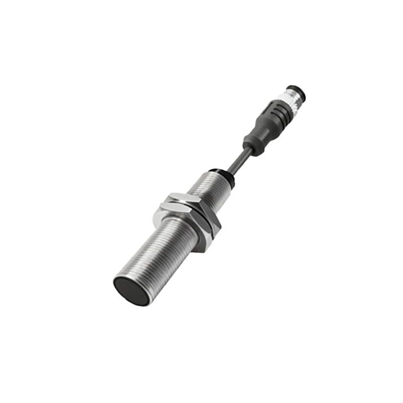
Before connecting a proximity sensor to a control system like a Programmable Logic Controller (PLC), it is crucial to understand its key specifications. The first is the operating voltage, typically ranging from 10-30V DC or 90-250V AC. DC sensors are far more prevalent in modern industrial automation. The second is the output type, which falls into two main categories: NPN (sinking) and PNP (sourcing). An NPN sensor switches the negative (0V) line to the load, while a PNP sensor switches the positive voltage line. The third is the output configuration: normally open (NO) or normally closed (NC). In a NO configuration, the output circuit is open (off) when no target is present and closes (on) when a target is detected. The opposite is true for NC. The sensor's datasheet will clearly indicate these parameters, along with the maximum output current, often around 200mA, which is sufficient to drive a PLC input or a small relay directly.
Standard Two-Wire and Three-Wire Connection Diagrams
Proximity sensors are primarily available in two-wire and three-wire designs. Two-wire sensors are simpler, connecting in series with the load and the power supply, similar to a mechanical switch. They are often used with AC power and have a small residual leakage current even when off, which must be considered when connecting to highly sensitive PLC inputs. Three-wire sensors are the standard for DC systems and offer superior performance. They have separate wires for power supply positive (brown wire typically), power supply negative/0V (blue wire), and the output signal (black wire). For a PNP sensor (sourcing), the black wire provides positive voltage to the load when activated. The load (e.g., PLC input) is then connected between this black wire and the 0V (blue). For an NPN sensor (sinking), the black wire provides a path to 0V when activated. The load is connected between the positive supply (brown) and the black wire. Always adhere to the color codes specified by the manufacturer.
Interfacing with PLCs and Control Systems
Connecting a proximity switch to a PLC input module is a common task. For a 24V DC PLC system, a three-wire PNP sensor is frequently used. Connect the sensor's brown wire to the 24V DC positive terminal, the blue wire to the 0V/COM terminal. The sensor's black output wire is then connected directly to the designated PLC input channel (e.g., I0.0). An internal resistor in the PLC input completes the circuit to the PLC's internal 0V. For an NPN sensor, the wiring differs: the brown wire goes to 24V+, the blue wire to 0V, and the black wire connects to the PLC input. However, the PLC input's common (COM) terminal must be connected to 24V+ to provide a current path, as the NPN sensor sinks current into its output. Incorrectly matching PNP sensors with NPN-configured PLC inputs, or vice versa, will result in non-operation. Always verify the PLC input module's schematic.
Shielding, Cable Routing, and Noise Immunity
Proper installation is critical for reliable sensor operation, especially in electrically noisy environments found near motor drives, welding equipment, or large solenoids. Always use shielded cables for sensor connections, particularly for analog sensors or those with long cable runs. Connect the cable shield to a stable earth ground at one end only, preferably at the control panel, to prevent ground loops. Keep sensor cables separate from high-voltage AC power lines. If they must cross, do so at a 90-degree angle. Ensure the sensor is mounted securely and that only