Introduction to M4 Proximity Sensor Technology
The M4 series represents a significant advancement in inductive proximity sensor technology, designed for demanding industrial environments. These sensors operate on the principle of electromagnetic induction, generating an oscillating electromagnetic field from a coil within the sensing face. When a metallic target object enters this field, eddy currents are induced on the target's surface, causing a change in the oscillation amplitude. The sensor's internal circuitry detects this change and triggers a solid-state output switch. The "M4" designation typically refers to a compact, cylindrical housing with a 4mm diameter, offering a space-saving solution for applications with severe mounting constraints. Their robust construction, often featuring stainless steel or nickel-plated brass housings, ensures reliable operation amidst vibration, moisture, and temperature fluctuations common in factory automation, packaging machinery, and automotive assembly lines.
Core Technical Specifications and Performance
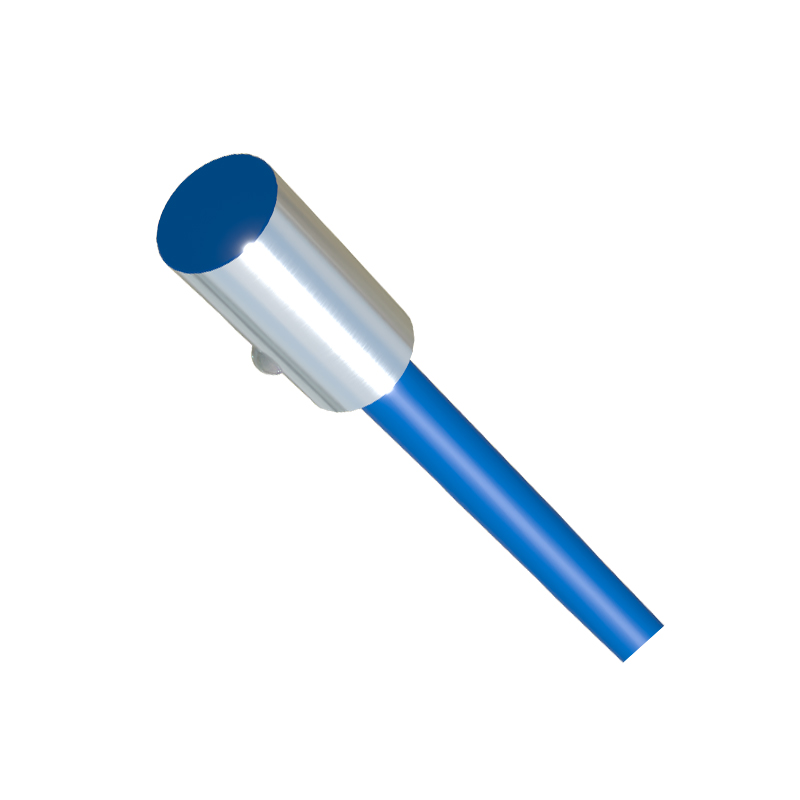
Key performance parameters define the M4 sensor's capability. The sensing range, while limited by its miniature size, is precisely calibrated, typically offering a nominal range of 0.8mm to 1.5mm for mild steel targets. Factors like target material, shape, and size significantly influence the effective sensing distance; for instance, the sensing range reduces for non-ferrous metals like aluminum or copper. Most M4 sensors feature a shielded (flush-mountable) design, allowing installation flush with a metal mounting surface without affecting performance. The operating voltage range is broad, commonly spanning from 10-30V DC, compatible with standard PLC and control system voltages. Output configurations include NPN (sinking) and PNP (sourcing) transistor outputs, as well as Normally Open (NO) or Normally Closed (NC) logic, providing flexibility for various control circuit designs. High switching frequencies, often up to 5kHz, enable detection of rapidly moving parts.
Wiring and Electrical Interface Standards
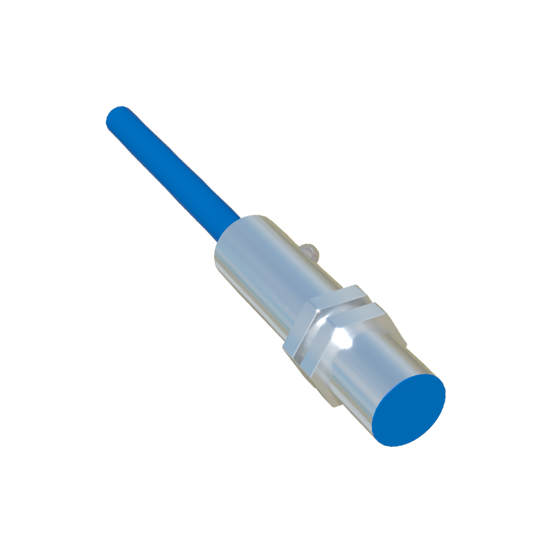
Correct wiring is paramount for reliable operation. Standard M4 proximity sensors utilize a 2-meter cable or a quick-disconnect connector system. The cable typically consists of three color-coded wires: brown for positive supply voltage (+V), blue for common negative (0V), and black for the switched output signal. For a 3-wire DC sensor, connecting brown to +24V DC and blue to 0V DC provides power. The black wire connects to the load (e.g., a PLC input module). The load is then connected back to the positive supply, completing the circuit. It is critical to observe the correct polarity and ensure the load current does not exceed the sensor's rated switching capacity, usually around 100-200mA. Incorporating protective devices like surge suppressors on inductive loads (relays, solenoids) is recommended to prevent voltage spikes from damaging the sensor's solid-state output.
Critical Selection Criteria for Application
Selecting the appropriate M4 sensor requires a detailed analysis of the application. First, identify the target material—ferrous, non-ferrous, or stainless steel—as this dictates the required sensing distance and may necessitate a factor-1 correction. The required mounting style, whether flush (shielded) or non-flush (unshielded), must be chosen based on the installation environment. Environmental conditions are crucial; an IP67 or IP68 ingress protection rating is standard for resistance to water and dust. The operating temperature range, typically -25°C to +70°C, must suit the ambient conditions. For high-speed counting or positioning, the sensor's response time and switching frequency must exceed the process speed. Finally, consider the electrical interface: PNP vs. NPN must match the control system's input card type to ensure proper signal interpretation.
Common Industrial Use Cases and Installations
M4 proximity sensors excel in precision detection tasks across numerous sectors. In semiconductor manufacturing, they verify the presence of tiny components on pick-and-place heads or circuit boards. Within automated assembly systems, they provide end-of-stroke detection for miniature pneumatic cylinders or confirm the position of small levers and cams. Robotics integrators use them as limit switches in robotic gripper jaws to detect if a part is securely held. In printing and packaging machinery, they monitor the rotation of small shafts or detect perforations on labels. A key installation best practice is to ensure the target approaches the sensor head perpendicularly for maximum range and repeatability. Maintaining a clean sensing face free of metal chips, grease, or adhesives is essential to prevent false triggering or reduced sensitivity.
Troubleshooting and Maintenance Guidelines
Despite their durability, M4