Understanding the Importance of Sensor Dimensions
In the realm of industrial automation and machine design, the physical size of a proximity sensor is far more than a mere specification on a datasheet. It is a critical parameter that directly influences the sensor's integration, performance, and suitability for a given application. Selecting a sensor with incorrect dimensions can lead to mounting difficulties, insufficient sensing range, or physical interference with moving parts. Therefore, a thorough understanding of how to read and interpret these dimensions is essential for any engineer or technician involved in system design, installation, or maintenance. This guide will break down the key dimensional parameters and provide practical insights for making informed decisions.
Deciphering the Standard Dimensional Parameters
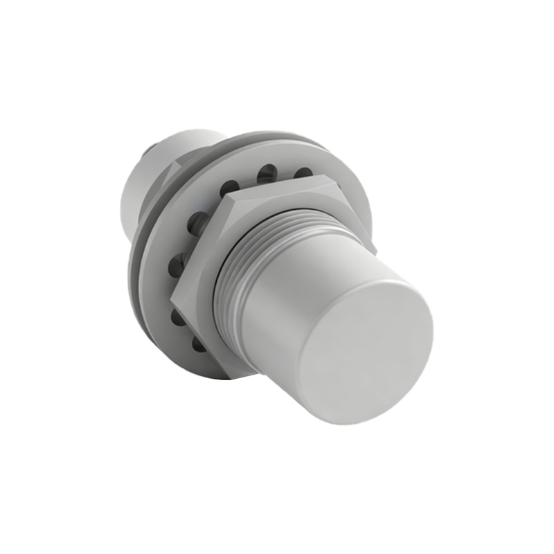
Proximity sensor datasheets typically present dimensions through detailed mechanical drawings. The primary parameters to focus on are the body diameter or housing size, the length, and the thread specifications. For cylindrical sensors, the body diameter (often denoted as M8, M12, M18, M30, etc.) is a standard metric thread size that dictates the required mounting hole. The length of the sensor, from the sensing face to the rear of the housing, determines how far it will protrude into or from the machine structure. Additionally, pay close attention to the flush-mountable or non-flush-mountable design, as this significantly affects the available sensing distance and mounting requirements. Non-flush sensors offer longer ranges but require clearance around the sensing face.
The Role of Sensing Range and Housing Material
While not a physical dimension in the traditional sense, the rated sensing range is intrinsically linked to the sensor's size. Generally, a larger sensor body can accommodate a larger coil (for inductive sensors) or more robust electronics, enabling a longer sensing distance. However, miniaturized sensors are continually pushing the boundaries, offering respectable ranges in tiny packages. The housing material, such as stainless steel, nickel-plated brass, or PBT plastic, also impacts the effective dimensions through its thickness and durability, which can affect resistance to mechanical stress and environmental factors like washdowns.
Mounting Considerations and Clearance Requirements
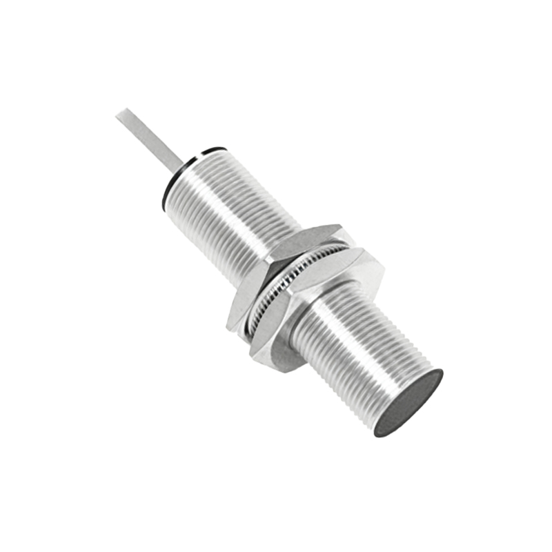
A crucial step often overlooked is verifying the necessary clearance around the sensor. The mechanical drawing will specify "side clearance" and "front clearance" requirements. Side clearance refers to the minimum distance required between the sensor body and any adjacent metal object (like the wall of the mounting hole or other machinery) to prevent false triggering or shielding effects. Front clearance is the space needed in front of the sensing face for the magnetic or electromagnetic field to develop properly. Ignoring these clearances can drastically reduce the sensor's effective range and reliability.
Connector and Cable Exit Dimensions
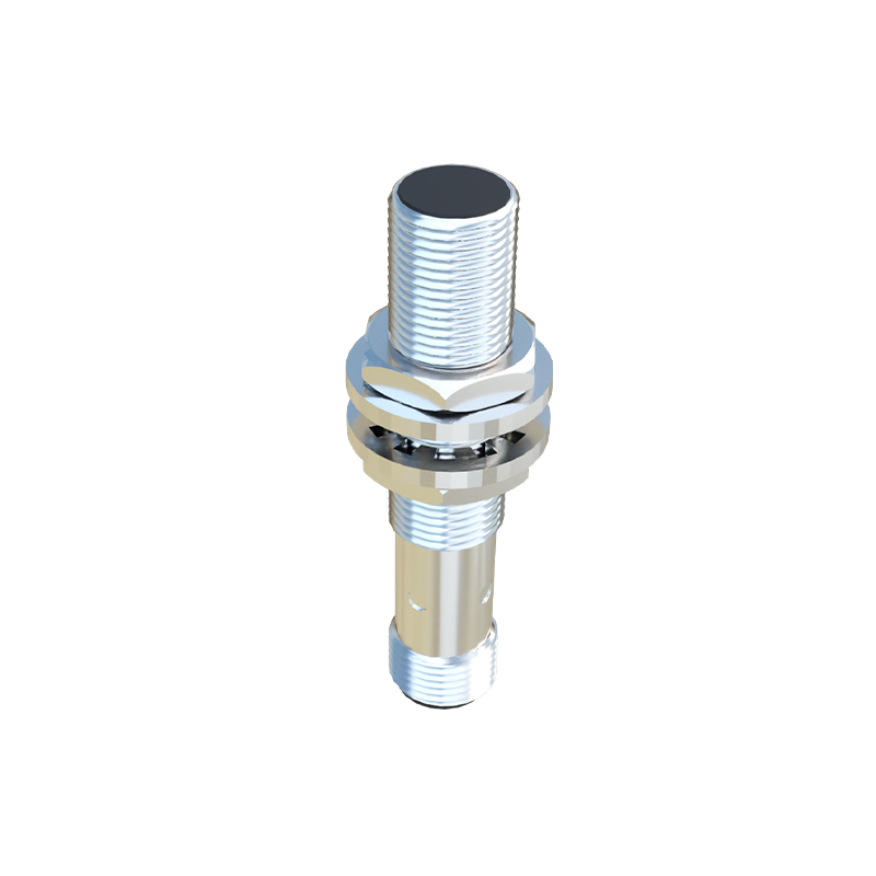
The connection method forms a vital part of the sensor's overall dimensional footprint. Sensors come with integrated cables of specified lengths and diameters, or with standardized quick-disconnect connectors (e.g., M12, M8 connectors). The type and orientation of the cable exit—axial (out the back), radial (out the side), or at a specific angle—must be considered for cable routing and space constraints. The dimensions and protrusion of the connector itself add to the sensor's effective installed length and must be accounted for in tight panels or moving assemblies.
Interpreting 2D Drawings and 3D Models
Modern sensor manufacturers almost always provide detailed 2D dimensional drawings (often in PDF format) and frequently offer 3D CAD models (STEP, SAT files). The 2D drawing is the legal document for specifications, containing all critical tolerances (± values) for dimensions. The 3D model is an invaluable tool for virtual integration, allowing engineers to perform clash detection and ensure proper fit within the digital prototype of the machine. Always cross-reference the key dimensions between the drawing and the model.
Application-Specific Dimensional Challenges
Specific applications impose unique dimensional constraints. In tight robotic end-effectors, ultra-miniature sensors (e.g., M5, M3) are necessary. For hydraulic cylinders, sensors with reduced "overall length" are required to fit within the cylinder's gland. In food and beverage applications, sensors with smooth, crevice-free housings of specific diameters are needed for hygiene. Always consider the operational environment: will thermal expansion affect clearances? Will vibration require a more robust, potentially larger housing? Answering these questions bridges the gap between theoretical dimensions and practical installation.
Practical Tips for Specification and Procurement
When selecting a sensor, create a simple checklist of dimensional requirements: 1) Available mounting hole size or space, 2) Required sensing range, 3) Necessary clearances (side/front), 4) Overall installed length including