Introduction to Zero-Wing Proximity Sensors
Zero-wing proximity switch sensors represent a specialized category within the vast field of industrial automation. Characterized by their compact, low-profile design without protruding "wings" or mounting flanges, these sensors are engineered for applications where space is at a premium. A visual examination of these sensors through detailed images reveals their unique construction. Typically, the housing is cylindrical and smooth, allowing for installation in tight cavities or directly through a panel with a simple nut. The sensing face is flush or nearly flush with the housing, which is a critical design aspect visible in cross-sectional diagrams. These images often highlight the embedded sensing coil and oscillator circuit, protected within a robust, often stainless steel or nickel-plated brass body. Understanding their physical form factor is the first step in appreciating their application-specific advantages.
Key Visual Features and Design Elements
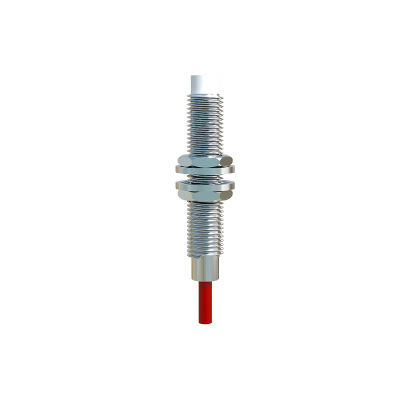
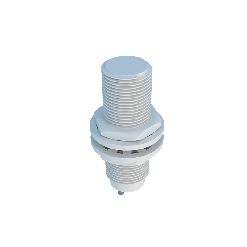
High-resolution photographs of zero-wing proximity sensors provide invaluable insights into their build quality and key features. The most prominent visual element is the absence of external mounting brackets. Instead, close-up images show a threaded barrel for installation. Many product images display the LED indicator, a small but crucial component usually located at the rear of the sensor, which provides visual confirmation of the switching state—crucial for debugging and setup. Color is also a distinguishing factor; many models feature a distinctive blue PBT or black plastic sensing face. Cutaway or exploded-view images are particularly educational, revealing the internal potting compound that protects the electronics from vibration, moisture, and chemical exposure. These visuals underscore the sensor's durability and suitability for harsh industrial environments.
Wiring and Connection Diagrams
Beyond the physical sensor, schematic diagrams and connection images are essential for proper implementation. Standard wiring diagrams depict the three primary connection types: 2-wire, 3-wire (NPN or PNP), and 4-wire (dual-channel) configurations. These diagrams use internationally recognized symbols to represent the power supply (typically 10-30V DC), load (such as a PLC input or relay), and the sensor itself. Accompanying photos of the sensor's cable outlet or connector style (e.g., M8 or M12 quick-disconnect) are equally important. They show the cable gland or integrated PUR cable, which provides strain relief. For engineers, these images serve as a direct reference for panel design and electrical integration, ensuring correct polarity and circuit protection to prevent damage.
Installation and Mounting Scenarios
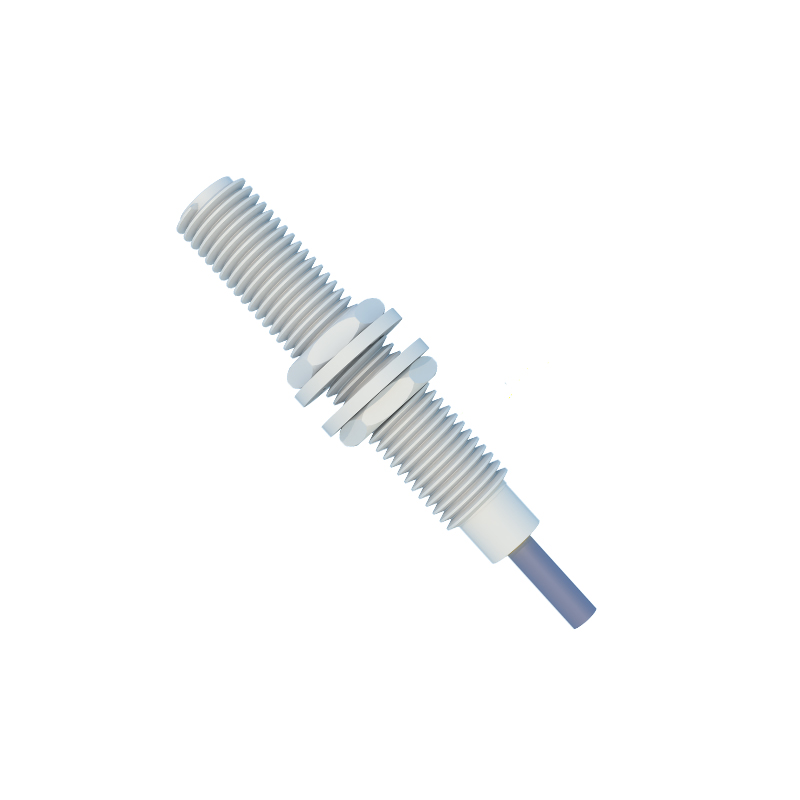
Application-oriented images demonstrate the practical installation of zero-wing proximity sensors. Common visuals include the sensor being threaded into a drilled hole on a machine frame, with only its sensing face exposed. Comparative images might show a standard tubular sensor with mounting brackets versus a zero-wing model, clearly illustrating the space savings. Other practical photos depict sensors mounted on robotic arms, within compact linear actuators, or on conveyor system side panels where clearance is minimal. These real-world images often include a target object, such as a metal gear tooth or a machine part, positioned at the specified sensing distance. Annotations on these photos frequently indicate the recommended mounting recess and the necessary clearance around the sensing face to prevent interference from surrounding metal, a key factor for reliable operation.
Target Detection and Sensing Range Visualization
Technical diagrams are vital for understanding the sensing field characteristics. Unlike simple photos, these illustrations often show the electromagnetic field pattern emitted from the sensor's face. For inductive zero-wing sensors (designed for metal targets), the diagrams depict the nominal sensing range (Sn) as a defined distance, often marked with precise millimeter measurements. They also illustrate the reduction factor for different metals, like steel, aluminum, or copper. For capacitive models (for non-metallic materials), images might show the adjustment potentiometer for sensitivity tuning. Side-view diagrams frequently include the "hysteresis" zone, the difference between the switch-on and switch-off points, which is critical for understanding repeatability and preventing signal chatter in dynamic applications.
Application-Specific Image Galleries
A gallery of application photos is perhaps the most convincing evidence of a zero-wing sensor's utility. These images cover diverse industries: close-ups in automotive assembly lines detecting piston position, sensors embedded in packaging machinery to count plastic bottles, or units installed on CNC lathes for tool positioning. In food and beverage applications, images showcase sensors with FDA-approved seals detecting fill levels. Each photo tells a story of solving a spatial constraint problem. High-speed sequence images or strobe-light photographs can even capture the moment of detection, showing the sensor's LED activating as a target passes by. These galleries help engineers visualize the sensor not as an isolated component but as an integral part of a larger, functioning system.