Introduction to M12 4-Pin Proximity Sensors
M12 4-pin proximity sensors represent a fundamental component in modern industrial automation, renowned for their compact design and reliable non-contact detection capabilities. These sensors utilize an M12 threaded cylindrical housing, which is a global standard for sensor connectivity, ensuring easy installation and compatibility with a vast array of industrial machinery and control systems. The 4-pin configuration is specifically engineered to support sensors that require both a switching output and an additional function, such as a diagnostic LED indicator, a teach-in function for parameter adjustment, or a short-circuit protection signal. This design offers greater functionality compared to the basic 2-wire or 3-wire variants, making them suitable for more complex control tasks. Typically constructed from robust materials like nickel-plated brass or stainless steel, they provide excellent resistance to vibration, shock, and harsh environmental conditions commonly found in manufacturing plants, packaging lines, and automotive assembly facilities.
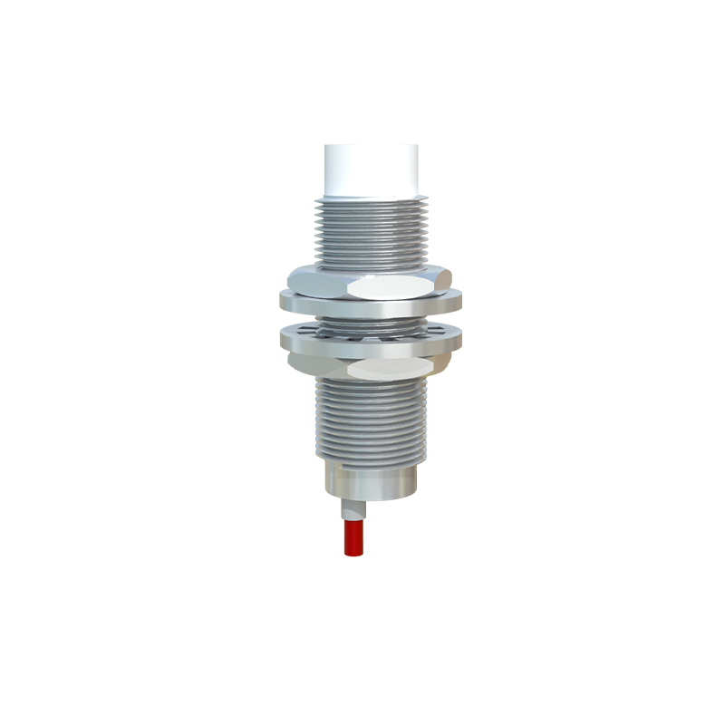
Working Principle and Sensing Technologies
The core operation of an M12 inductive proximity sensor revolves around electromagnetic induction. The sensor's face contains an oscillator coil that generates a high-frequency electromagnetic field. When a metallic target object enters this active field, eddy currents are induced on the target's surface. This causes a change in the oscillation amplitude within the sensor, which is detected by a threshold circuit. This circuit then triggers a solid-state switch, changing the output state. For M12 4-pin models, this output is typically a discrete PNP (sourcing) or NPN (sinking) signal. The fourth pin is often allocated for a separate function. In some advanced models, it provides a complementary NO/NC output, allowing for more flexible wiring into programmable logic controllers (PLCs). Other technologies available in the M12 form factor include capacitive sensors for non-metallic object detection and ultrasonic sensors for distance measurement, though the inductive type remains the most prevalent for metal detection applications.
Electrical Characteristics and Wiring Configuration
Understanding the pinout and electrical specifications is critical for correct integration. The standard pin assignment for a 4-pin M12 connector, following the IEC 60947-5-2 norm, is as follows: Pin 1 is typically for the positive supply voltage (V+), Pin 2 is for the output signal 1, Pin 3 is for the 0V supply (GND), and Pin 4 is reserved for the auxiliary function, which could be a second output, an input for diagnostics, or a teach-in wire. Operating voltages commonly range from 10-30V DC. The output is a solid-state transistor switch capable of handling currents up to 200mA, sufficient to directly drive small relays, PLC inputs, or indicator lamps. Wiring diagrams must be consulted meticulously, as the function of Pin 4 can vary significantly between manufacturers and sensor models. Proper shielding and cable routing are essential to prevent electromagnetic interference (EMI) from affecting the sensor's performance, especially in environments with high-power motor drives or frequency converters.
Key Selection Criteria for Application
Selecting the appropriate M12 4-pin sensor requires a detailed analysis of the application parameters. The first consideration is the sensing distance, or nominal range, which must be chosen with a safety margin to account for target material, size, and possible installation tolerances. The second is the target material; standard inductive sensors are optimized for steel, with reduction factors applied for other metals like aluminum or copper. The housing material is another vital factor; stainless steel versions offer superior chemical and corrosion resistance for washdown areas in food & beverage or pharmaceutical industries. The switching frequency, or response time, determines how fast the sensor can detect objects on a high-speed production line. Environmental ratings, denoted by IP (Ingress Protection) and IK (Impact Protection) codes, indicate the level of protection against dust, water, and mechanical impact. For instance, an IP67 rating guarantees protection against temporary immersion, which is crucial for many industrial settings.
Installation, Alignment, and Maintenance Best Practices
Correct installation is paramount for optimal sensor performance and longevity. The sensor should be mounted securely using its M12 thread, ensuring it is not subjected to excessive side-load or torque. A critical rule is to maintain the recommended lateral and axial clearance from surrounding metal objects to prevent false triggering or shielding effects. Alignment between the sensor face and the target should be as perpendicular as possible to achieve the stated sensing range. For maintenance, these sensors are largely maintenance-free due to their solid-state design. However, periodic checks are advised to verify mechanical integrity, clean the sensing face from accumulated debris, and confirm electrical connections are tight and free from corrosion. Diagnostic