Introduction to Proximity Sensing Technology
Proximity sensors are indispensable components in modern industrial automation, robotics, and safety systems. Their primary function is to detect the presence or absence of an object within a specified range without any physical contact. This non-contact detection capability offers significant advantages, including high reliability, long operational life, and the ability to function in harsh environments where contaminants, moisture, or mechanical wear would compromise physical switches. The core of understanding how these devices operate lies in analyzing their sensing principle diagrams. These schematics translate the abstract detection concept into a concrete electrical and magnetic model, detailing the interaction between the sensor's internal oscillator, detection coil or element, and the target object. For electrical engineers, mastering these diagrams is crucial for proper sensor selection, circuit integration, and troubleshooting.
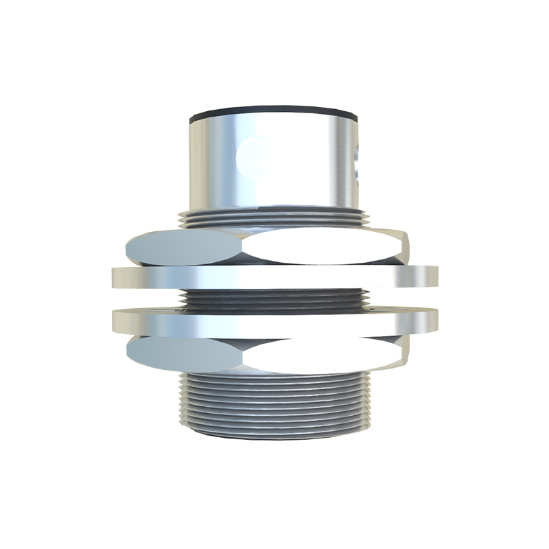
Core Components in a Principle Diagram
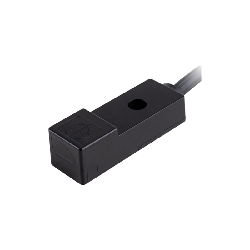
A standard proximity sensor sensing principle diagram, particularly for the widely used inductive type, breaks down the device into several key functional blocks. The central element is the LC oscillator circuit, comprising an inductor (the sensing coil) and a capacitor. This oscillator generates a high-frequency electromagnetic field that emanates from the sensor's active face. The diagram clearly shows the oscillator connected to a detection circuit, often a Schmitt trigger or a comparator. This circuit monitors the amplitude of the oscillator's signal. Another critical block is the output stage, which could be a transistor (PNP or NPN for DC sensors) or a solid-state relay. The diagram also includes power supply connections (Vcc and GND) and the output load connection. Understanding the signal flow from the oscillator, through the detector, to the output driver is fundamental.
Inductive Sensor Operation and Diagram Analysis
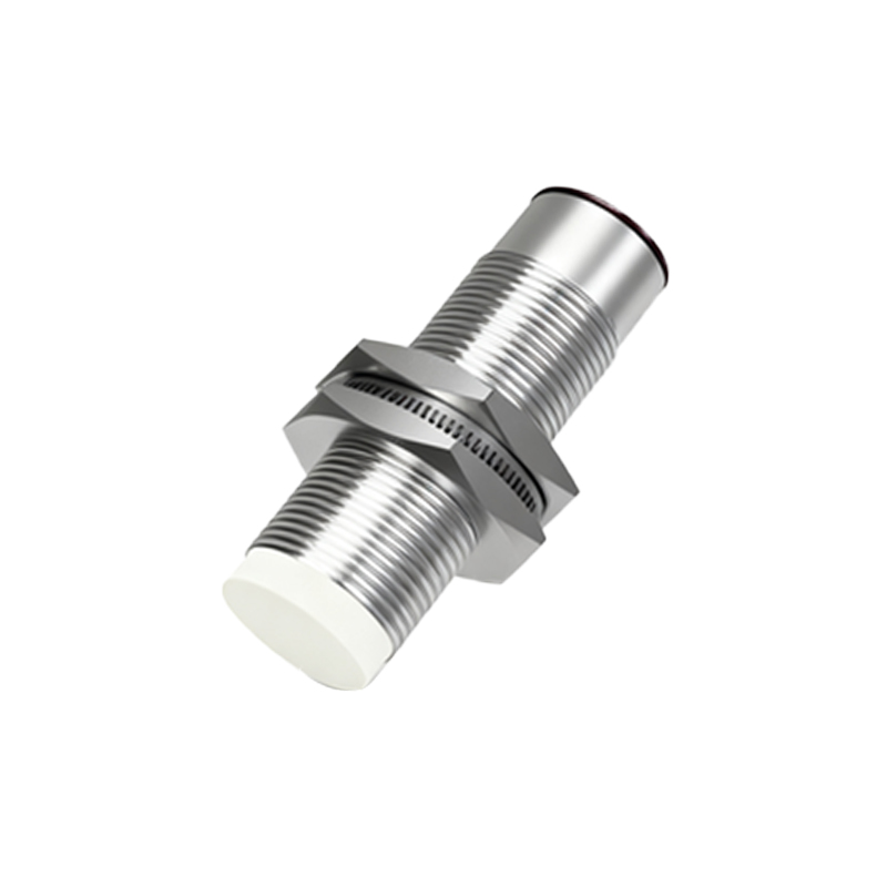
Inductive proximity sensors are designed to detect metallic objects. The principle diagram visually explains the detection process. When no target is present, the LC oscillator runs at its designed frequency and amplitude, as shown by a stable waveform in the diagram. The detection circuit interprets this as a "no object" state, and the output stage remains inactive. When a conductive metal target enters the sensor's electromagnetic field, eddy currents are induced on the target's surface. The principle diagram illustrates this as a load on the oscillator coil, symbolizing energy loss. This loss causes the amplitude of the oscillator's oscillations to decrease. The detection circuit is calibrated to sense this specific amplitude drop. Once the threshold is crossed, the detection circuit triggers the output stage to switch state, for example, sinking current to ground in an NPN configuration. The diagram uses standard electrical symbols to depict this switching action, showing the path for the output current.
Capacitive Sensor Sensing Mechanism
Capacitive proximity sensors can detect both metallic and non-metallic objects, such as plastics, liquids, or wood. Their principle diagram differs from inductive types by focusing on capacitance change. The sensor face acts as one plate of a capacitor, with the target object acting as the other plate, and the air gap as the dielectric. The diagram typically shows an RC oscillator or a capacitance-to-voltage conversion circuit. As a target approaches, the effective capacitance between the sensor electrode and the target increases. The principle schematic details how this change in capacitance alters the frequency of an oscillator or the voltage level in a bridge circuit. This altered signal is fed into a threshold detector. When the change exceeds a set point, the output circuit is activated. The diagram highlights the sensitivity adjustment component, which allows tuning the sensor for different material types and application conditions.
Output Configuration Representation
The output section of a sensing principle diagram is vital for integration into control systems. Diagrams distinctly show the three main DC output types: NPN (sinking), PNP (sourcing), and push-pull. In an NPN diagram, the output transistor's emitter is connected to ground (0V), and the load is connected between the output wire (collector) and the positive supply. When active, the transistor sinks current from the load to ground. A PNP diagram shows the opposite: the emitter is connected to Vcc, and the load is connected between the output and ground. Analog output versions, like 4-20mA or 0-10V, are represented with a controlled current source or voltage regulator block in the diagram, showing how the sensor's analog signal is generated proportionally to the sensing distance or target presence.
Practical Application and Troubleshooting Insights
Interpreting the sensing principle diagram directly aids in practical application and diagnostics. For instance, the diagram explains why inductive sensors have a nominal sensing distance (Sn) and why factors like target material, size, and shape can affect it, as shown by the coupling efficiency in the magnetic field representation. When troubleshooting a malfunctioning sensor, an engineer can reference the