Understanding Hall Effect Proximity Switch Fundamentals
Hall effect proximity switches are critical components in modern industrial automation, offering non-contact detection of ferromagnetic and permanent magnet targets. Their operation relies on the Hall effect principle: when a current-carrying conductor is placed in a magnetic field, a voltage (the Hall voltage) is generated perpendicular to both the current and the field. In a proximity switch, a semiconductor Hall element senses changes in the magnetic field density caused by a target's approach. This triggers a solid-state electronic circuit to switch its output state, typically from high to low voltage or vice-versa. Their robustness, long operational life, and immunity to environmental contaminants like dust and oil make them preferred over mechanical limit switches in harsh environments. However, their solid-state nature does not render them immune to failure. A deep understanding of their working principle is the first step in effective troubleshooting.
Common Failure Modes and Root Causes
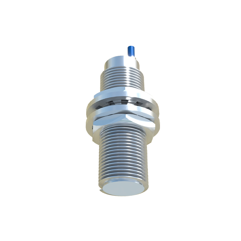
Failures in Hall effect sensors can be categorized into several distinct modes. Complete loss of output is a frequent issue. This can stem from internal semiconductor damage due to voltage transients or electrostatic discharge (ESD) during handling or installation. Sustained overvoltage conditions, often from faulty power supplies or wiring errors, can destroy the integrated circuitry. Another common failure is erratic or intermittent switching. This is frequently caused by electromagnetic interference (EMI) from nearby high-current cables, variable frequency drives (VFDs), or welding equipment. The sensor's output may chatter or trigger at incorrect distances. Physical damage, though less common due to non-contact operation, can occur from excessive vibration loosening internal connections or direct impact damaging the sensor housing and the delicate Hall chip inside. Lastly, performance degradation, such as a reduced sensing range, can indicate a weakening internal magnet (in self-contained units) or a buildup of metallic debris on the sensing face altering the magnetic field.
Systematic Electrical Troubleshooting Procedure
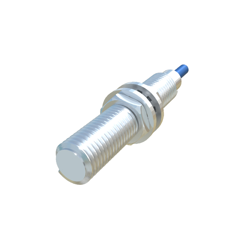
A methodical approach is essential for diagnosing Hall sensor issues. First, verify the power supply. Using a digital multimeter (DMM), confirm that the voltage at the sensor's terminals matches the specified range (e.g., 10-30 VDC). Incorrect polarity is a common installation error that can cause immediate failure. Next, check the output. For a 3-wire DC sensor, monitor the output voltage between the signal (black) wire and the negative (blue) wire. As a target is presented, the voltage should switch cleanly from near supply voltage (e.g., 24V) to near 0V for a sinking (NPN) type, or the opposite for a sourcing (PNP) type. A sluggish transition or a voltage that doesn't reach the expected extremes indicates a faulty output stage. Always consult the manufacturer's datasheet for specific wiring diagrams and voltage thresholds. If the electrical checks are inconclusive, proceed to environmental and mechanical inspections.
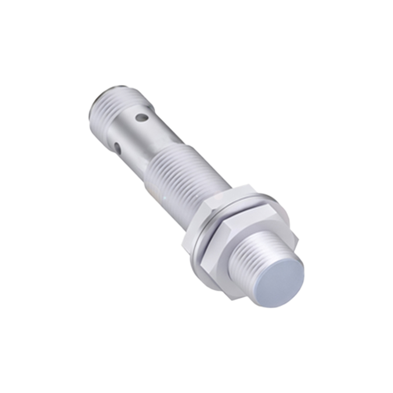
Environmental and Mechanical Inspection Points
The operating environment is a major contributor to sensor failure. Inspect the sensor face for accumulation of ferrous metal chips, dust, or other contaminants that can shield the magnetic field. Clean the face carefully with a non-metallic tool and a suitable solvent. Examine the installation for excessive vibration, which can fracture solder joints inside the sensor. Ensure the mounting brackets are secure. Verify the alignment between the sensor and the target. The target must pass within the specified sensing distance and should be of the correct material and size. A target that is too small, non-ferrous, or misaligned will not trigger the sensor reliably. Check for signs of overheating, such as discolored housing, which could indicate excessive current draw or ambient temperatures beyond the sensor's rating. Also, inspect the cable and connector for damage, pinched wires, or compromised seals that could allow moisture ingress, leading to corrosion and short circuits.
Interference Mitigation and Installation Best Practices
Electromagnetic interference is a pervasive challenge. To mitigate EMI, always use shielded cables for sensor connections and ground the shield at one end only, typically at the control panel. Maintain maximum physical separation between sensor cables and power lines, especially those feeding motors or drives. If cables must cross, ensure they do so at a 90-degree angle. Consider using ferrite cores on the sensor cables near the connector if interference is suspected. For sensors in high-vibration areas, use vibration-damping mounts. Ensure the sensor is not being used to detect targets moving at speeds exceeding its maximum switching frequency, as this can cause missed counts. When replacing a sensor, always match the output type (NPN vs. PNP), voltage range, and sensing distance precisely. Implementing these best practices during installation can prevent a majority of field failures and ensure long-term, reliable