Introduction to Inductive Proximity Sensors
Inductive proximity sensors are fundamental components in industrial automation, renowned for their non-contact detection of metallic objects. Operating on the principle of electromagnetic induction, these sensors generate an oscillating electromagnetic field from a coil. When a metallic target enters this field, eddy currents are induced within the target, causing a change in the oscillation amplitude. This change is detected by the sensor's circuitry, triggering a solid-state output signal. The M18 form factor, with its 18mm diameter threaded barrel, is one of the most prevalent and versatile housings in the industry, offering an optimal balance between sensing range, physical robustness, and mounting flexibility.
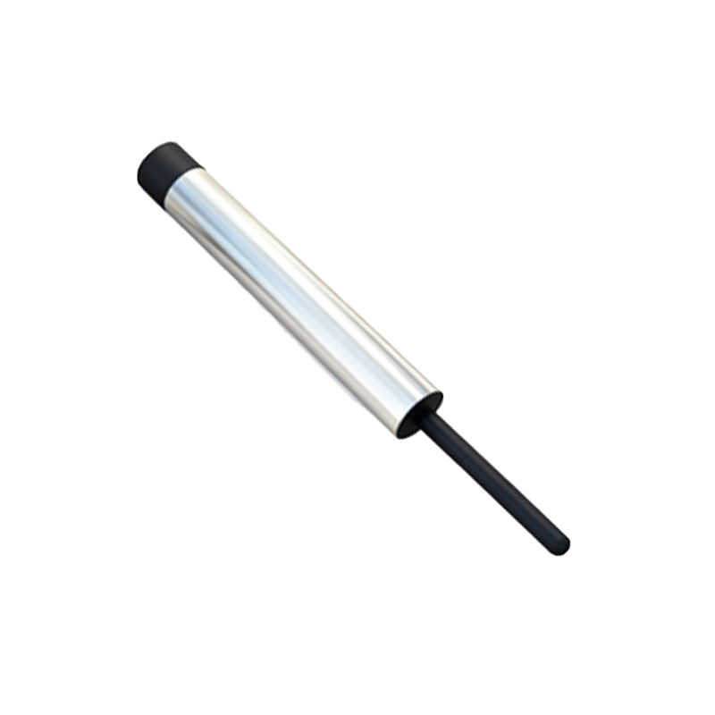
Defining the Flush Mount (Non-Flush) Design
The M18 inductive proximity sensor is commonly available in two mounting styles: flush mount (also referred to as non-flush or shielded) and non-flush mount (unshielded). A flush mount M18 sensor is characterized by its shielded sensing face. This shielding, typically a metallic ring surrounding the active sensing element, contains the electromagnetic field, preventing it from radiating laterally. This crucial design feature allows the sensor to be installed flush with, or even embedded within, a metal mounting surface without causing false triggers. The sensing field projects directly forward from the face, making it ideal for applications where the sensor must be protected from physical damage or where mounting space is constrained within metallic structures.
Key Technical Specifications and Performance
The performance of an M18 flush mount inductive sensor is defined by several key parameters. The nominal sensing distance (Sn) for a standard M18 flush mount sensor is typically 5mm or 8mm, though specialized models may vary. It is critical to note that the effective sensing range can be reduced when installed in a metal cavity. These sensors are designed to detect ferrous metals (like iron and steel) at their rated sensing distance, while non-ferrous metals (such as aluminum, copper, or brass) are detected at a reduced range, often 30-50% of Sn. Operating voltage ranges are broad, commonly covering 10-30V DC or 20-250V AC. The output is usually a solid-state PNP (sourcing) or NPN (sinking) transistor for DC models, or a relay for AC models, with standard configurations being normally open (NO) or normally closed (NC).
Advantages of the Flush Mount Configuration
The primary advantage of the flush mount M18 sensor is its immunity to surrounding metal. It can be installed without any lateral clearance (side clearance) from adjacent metal surfaces, simplifying mechanical design and allowing for very compact installations. This shielding also enhances its resistance to physical impacts and environmental contaminants, as the sensing face can be mounted level with a protective metal bracket. Furthermore, the directed sensing field minimizes the risk of unintended detection of objects passing beside the sensor, increasing operational reliability in dense machinery layouts. Its robust construction typically ensures high protection ratings, such as IP67 or IP69K, making it suitable for harsh environments involving washdowns, coolants, or dust.
Typical Industrial Applications
M18 flush mount inductive sensors are ubiquitous across manufacturing and processing industries. Common applications include position verification of metal parts on conveyor lines, end-of-travel detection for cylinders and actuators, tool presence detection in CNC machining centers and automated tool changers, and counting of metal components. They are extensively used in metal stamping, packaging machinery, automotive assembly lines, and material handling systems. Their flush mount capability makes them indispensable for integration into metal machine frames, robotic end-effectors, and safety guarding systems where sensors must not protrude and risk being sheared off.
Installation and Wiring Considerations
Proper installation is paramount for reliable operation. The sensor should be mounted securely using its standard M18 x 1 thread. While no lateral clearance is required, it is essential to maintain the specified front clearance—the minimum distance between the sensor face and the target during approach—to ensure stable switching. For flush mounting in a metal panel, the mounting hole should be drilled to the correct diameter to ensure a snug fit. Wiring must adhere to the manufacturer's diagram, paying close attention to the polarity for DC sensors (brown wire to +V, blue wire to 0V, black wire as output). Always implement electrical protection, such as surge suppressors for DC models or fuses for AC models, especially in environments with inductive loads like solenoids or motors.
Troubleshooting Common Issues
Several common issues can affect M18 flush mount sensors. Failure to detect a target may result from an insufficient target size (must be