Understanding Proximity Switch Sensor Basics
Proximity switch sensors are essential components in industrial automation, detecting the presence or absence of objects without physical contact. These sensors operate on principles such as inductive, capacitive, or magnetic fields, making them ideal for harsh environments. Before wiring, it is crucial to identify the sensor type (e.g., NPN or PNP output) and voltage rating (typically 10-30V DC or 90-250V AC). Always refer to the manufacturer's datasheet for specific specifications, as incorrect wiring can lead to sensor failure or system malfunctions. Safety precautions, including disconnecting power and using appropriate personal protective equipment (PPE), must be observed throughout the installation process.
Pre-Wiring Preparation and Tools Required
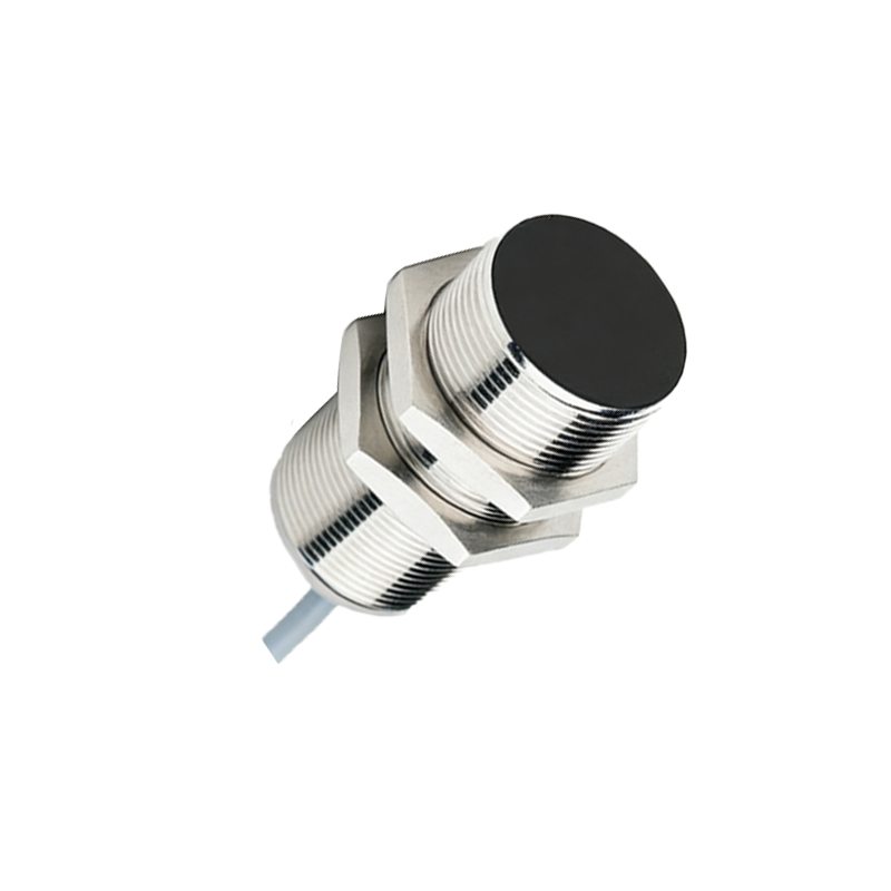
Proper preparation ensures a smooth wiring process. Gather necessary tools: wire strippers, screwdrivers, multimeter, and terminal blocks. Check the sensor's housing for IP ratings to confirm suitability for the environment (e.g., dust or moisture resistance). Verify the control system's compatibility—most industrial setups use programmable logic controllers (PLCs) or relays. Label wires according to color codes: brown for positive (+), blue for negative (-), and black for output signal. For AC sensors, brown is live (L), blue is neutral (N), and black is the output. Ensure all components are rated for the operational voltage and current to prevent overheating or short circuits.
Wiring Inductive Proximity Sensors (DC Models)
Inductive sensors are common for metal detection. For DC models, start by connecting the power supply. Attach the brown wire to the positive terminal (+) and the blue wire to the negative terminal (-) of the DC power source. The black wire carries the output signal to the load (e.g., PLC input). In NPN sensors, the output switches the negative side, meaning the black wire connects to the load, which is then linked to positive voltage. For PNP sensors, the output switches the positive side, so the black wire connects to the load, and the load ties to ground. Always use shielded cables in electrically noisy environments to reduce interference, and ground the shield at one end only.
Wiring Capacitive and Magnetic Proximity Sensors
Capacitive sensors detect non-metallic materials and follow similar wiring patterns but may include sensitivity adjustments. For DC capacitive sensors, connect brown to positive, blue to negative, and black to the load. Magnetic sensors (e.g., reed switches) often have two wires: one for power and one for output. Wire them in series with the load and power supply, ensuring polarity matches if specified. For AC-powered capacitive or magnetic sensors, connect brown to live (L), blue to neutral (N), and black to the load. Incorporate a surge protector if the sensor is exposed to voltage spikes, and test with a multimeter to verify continuity and correct voltage levels before full operation.
Integrating Sensors with PLCs and Control Systems
To interface with PLCs, identify the input type (sourcing or sinking). For NPN sensors (sinking output), connect the black wire to the PLC input terminal, and link the PLC common to positive voltage. For PNP sensors (sourcing output), connect the black wire to the PLC input, and link the PLC common to ground. Use terminal blocks for organized connections, and avoid loose wires that could cause disconnections. Program the PLC to recognize the sensor signal, setting appropriate delay times to debounce inputs. For relay-based systems, wire the sensor output to the relay coil, ensuring the coil voltage matches the sensor output. Always follow ladder logic or control diagrams to prevent wiring errors.
Troubleshooting Common Wiring Issues
After wiring, test the system systematically. If the sensor fails to detect objects, check power connections with a multimeter—ensure voltage is within range. Inspect for loose wires or corrosion at terminals. For false triggers, assess environmental factors like electromagnetic interference (EMI) and reposition cables away from motors or high-voltage lines. Verify the sensing distance aligns with the object's properties; adjust sensitivity if available. If the output is inconsistent, confirm the load compatibility—overloading can damage the sensor. Consult error codes in the datasheet, and consider using an oscilloscope to analyze signal integrity in complex setups. Regular maintenance, including cleaning and recalibration, prolongs sensor life.
Best Practices for Safe and Efficient Installation
Adhere to industry standards such as IEC 60947 for switchgear and control devices. Use conduit or cable trays to protect wires from physical damage, and ensure proper grounding