Introduction to Proximity Sensor Wiring
Proximity sensors are fundamental components in industrial automation, providing non-contact detection of metallic or non-metallic objects. A correct and reliable wiring connection is paramount for their optimal performance and system safety. Among various wiring methods, the direct connection, or 2-wire configuration, is widely used for its simplicity and cost-effectiveness. This guide details the standard wiring diagram for directly connecting a proximity sensor, explaining the core principles, necessary components, and step-by-step implementation procedures. Understanding this diagram is essential for engineers and technicians involved in machine design, maintenance, and troubleshooting.
Core Components and Electrical Specifications
A typical 2-wire AC proximity sensor has two terminals: one for the line (L) or phase connection and one for the load. Unlike 3-wire sensors with separate power and signal lines, the 2-wire sensor is connected in series with the load (e.g., a PLC input, relay coil, or indicator lamp). It is crucial to first verify the sensor's specifications on its datasheet: operating voltage (commonly 120VAC or 240VAC), current rating, and leakage current. The sensor acts as a switch; when no target is present, it has a small leakage current. When a target enters its sensing range, it "closes," allowing the full load current to flow. The connected load must have a minimum current requirement (often 5mA or more) to ensure the sensor can turn on properly, and a maximum current limit to prevent damage.
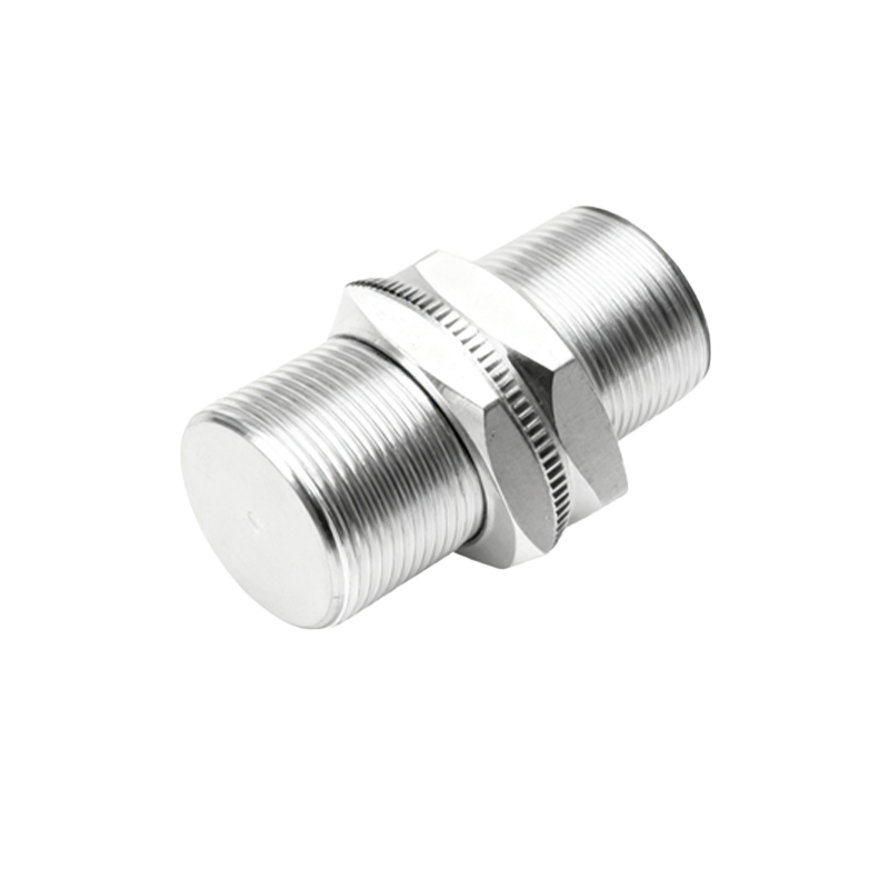
Standard Direct Connection Wiring Diagram
The standard wiring diagram for a direct connection is straightforward. The power source (e.g., 120VAC) connects to one terminal of the sensor. The other terminal of the sensor connects to one terminal of the load device. The remaining terminal of the load device then connects back to the neutral (N) of the power source, completing the circuit. It is vital to incorporate a fuse or circuit breaker in the line (hot) conductor before the sensor for overload protection. Some diagrams also show a protective earth (PE) ground connection to the sensor's housing if it is metal, which is a critical safety measure. The load, in many control applications, is the input module of a Programmable Logic Controller (PLC). The sensor essentially controls the power to this PLC input.
Step-by-Step Installation Procedure
Begin by ensuring the main power supply is locked out and tagged out (LOTO) to prevent accidental energization. Identify the sensor's terminals, usually labeled as "1" and "2" or with symbols. Using appropriate gauge wires, connect the phase (hot) wire from the fused power source to terminal "1". Connect a wire from terminal "2" to one side of your load (e.g., terminal "A1" on a PLC digital input card). Finally, connect the other side of the load back to the power supply's neutral. Securely tighten all connections. For metal-bodied sensors, connect a separate ground wire from the housing's ground terminal to the facility's grounding system. Always follow the specific manufacturer's instructions provided with the sensor.
Critical Considerations for Reliable Operation
Several factors influence the reliability of a direct-wired proximity sensor. Leakage Current: 2-wire sensors have inherent leakage current (typically 1-2mA). If the load's minimum operating current is too high, the sensor may fail to turn the load on fully, causing erratic behavior. Load Compatibility: Ensure the load (relay, PLC input) is compatible with AC or DC as per the sensor type. Mixing AC sensors with DC loads, or vice-versa, will not work. Short-Circuit Protection: Always use a correctly rated fuse. A short circuit in the sensor or wiring could damage the power supply and create a fire hazard. Electrical Noise: In environments with heavy machinery (motors, welders), use shielded cable and ground the shield at one end to prevent electromagnetic interference from causing false triggering.
Common Troubleshooting Scenarios
When a directly connected proximity sensor malfunctions, a systematic approach is key. Sensor Not Triggering: First, check for power at the sensor terminals using a multimeter. Verify the target is within the sensing range and is of the correct material. Measure the voltage across the load when the sensor should be active; a low voltage indicates the sensor may not be switching fully, often due to insufficient load current. Sensor Stays On: This can be caused by excessive leakage current tricking a high-impedance load. Adding a "bleeder" or "load resistor" in parallel with the load can often solve this by ensuring the minimum current