Understanding Proximity Sensor Core Power Requirements
The magnetic core, often a ferrite or laminated steel component, is the heart of an inductive proximity sensor. It concentrates the magnetic field generated by the sensor's coil. Importantly, the core itself is a passive element and does not have its own power pins. The power connection is made to the sensor's electronic circuitry, which then energizes the coil wound around that core. Therefore, discussing how to "power the core" inherently means powering the entire sensor assembly. The first critical step is always to consult the sensor's datasheet. Key specifications to identify are the operating voltage range (e.g., 10-30V DC, 20-250V AC), current consumption, and whether it is a 2-wire, 3-wire, or 4-wire device. Mismatching voltage or wiring can lead to immediate failure or unreliable operation.
Wiring Configurations: 2-Wire, 3-Wire, and 4-Wire Sensors
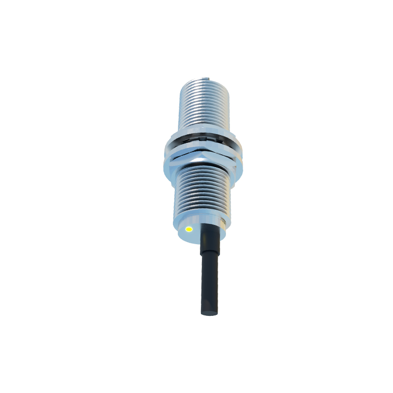
The wiring configuration dictates the power connection methodology. For a 2-wire DC sensor, the device is connected in series with the load (like a PLC input). It requires a voltage supply, and the sensor uses the same two wires for both operating power and signal switching. Polarity is often not critical for AC 2-wire models, but it is absolutely crucial for DC models; the brown wire (typically) connects to positive (+), and the blue wire to negative (-). A 3-wire DC sensor is the most common. It has separate wires for power and output. Connect the brown wire to the positive DC supply, the blue wire to the negative DC supply (0V), and the black wire is the switched output that connects to your load. The load's other side returns to the negative supply. For 4-wire sensors, which contain two separate outputs (e.g., one Normally Open and one Normally Closed), the principle is the same: brown to +V, blue to 0V, with the black and white wires providing the dual output signals.
Selecting and Connecting the Power Supply
A stable, regulated DC power supply is highly recommended for consistent sensor performance. Choose a supply with a voltage rating within the sensor's specified range, often 24V DC as an industry standard. The power supply must be capable of delivering current greater than the sum of all connected sensor currents. When connecting, ensure proper wire gauge to minimize voltage drop, especially over long distances. Always implement protective measures. A fast-blow fuse (rated slightly above the total current draw) in the positive line is essential for short-circuit protection. For DC sensors, adding a reverse polarity protection diode across the supply inputs can prevent damage from accidental miswiring. In electrically noisy environments, consider using a shielded cable, grounding the shield at the power supply end only.
Integrating the Load and Completing the Circuit
The sensor's output is a switch that controls the load, which is often a programmable logic controller (PLC) input, a relay coil, or an indicator lamp. For a 3-wire NPN (sinking) output sensor, the black output wire switches the negative side. The load is connected between the positive supply and the black wire. When the sensor activates, it connects the black wire to 0V (blue wire), completing the circuit to energize the load. For a PNP (sourcing) output sensor, the black wire switches the positive side. The load is connected between the black wire and the 0V supply. Understanding this distinction is vital for proper integration. Always verify the load's voltage and current ratings are compatible with the sensor's switching capacity.
Best Practices for Installation and Troubleshooting
Prior to applying power, double-check all wiring against the manufacturer's diagram. Use a multimeter to check for short circuits between wires. Upon first power-up, observe the sensor's indicator LED (if present). A steady or blinking light usually indicates correct power and standby operation. Common issues include no power, often due to incorrect polarity, blown fuse, or insufficient voltage. Erratic switching can be caused by electrical noise, grounding problems, or a metal object vibrating near the sensing face. Ensure the sensor is mounted securely and that the target material and size are appropriate for the sensor's rated sensing distance. Regular maintenance involves checking connection integrity and cleaning the sensing face from contaminants like metal dust or oil, which can affect performance.