Understanding the Green LED Indicator on Proximity Sensors
In industrial automation, proximity switch sensors are critical components for non-contact detection. A key feature of many modern models is a built-in LED indicator, often green, which provides immediate visual feedback on the sensor's operational status. This light serves as a diagnostic tool, communicating power status, output state, and potential errors. A steady green light typically indicates normal operation—the sensor is powered, functioning correctly, and its output is inactive (or active, depending on the wiring logic). However, when this green LED begins to flash in a specific pattern, it is conveying a deliberate message that requires the technician's attention. Understanding these signals is the first step in effective troubleshooting and maintaining seamless production line performance.
Decoding Common Flashing Patterns and Their Meanings

A flashing green light is not a random occurrence; it is a coded signal. The pattern—whether it's a slow blink, a rapid flash, or a series of long and short pulses—holds specific meaning defined in the sensor's manual. A common pattern, such as a slow, single flash repeated at intervals, might indicate a "short-circuit" or "overload" condition at the output. This happens when the load connected to the sensor's output (like a relay or PLC input) draws excessive current, triggering the sensor's internal protection. A rapid, continuous flashing could signal a "supply voltage" issue, such as under-voltage or over-voltage, where the input power falls outside the sensor's specified operating range. Another pattern might indicate a "sensor error" like internal oscillation failure or temperature drift beyond limits. Always consult the specific product datasheet to interpret the exact code.
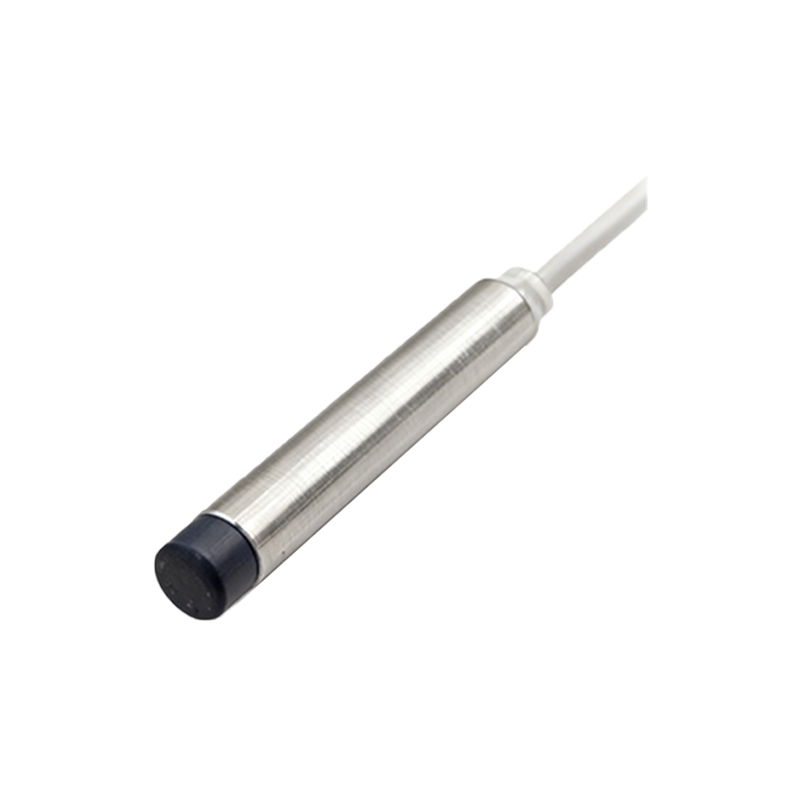
Primary Causes of a Flashing Green LED
Several root causes can trigger the diagnostic flashing mode. The most frequent culprit is an electrical fault in the wiring or load. An output short-circuit, caused by damaged cable insulation or incorrect wiring to the load, is a prime example. Similarly, connecting a load that exceeds the sensor's maximum switching current or leakage current from an inductive load can simulate an overload condition. Power supply problems are equally common. Using an unregulated or noisy power supply, experiencing voltage dips from large machinery startups, or having loose connections can cause the voltage at the sensor terminals to fluctuate, prompting a voltage error flash. Less commonly, environmental factors like extreme electromagnetic interference (EMI) from nearby drives or welders, or excessive ambient temperature, can interfere with the sensor's internal circuitry, causing it to flag an error.
Systematic Troubleshooting Procedure
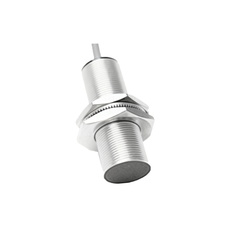
When faced with a flashing green LED, follow a logical, step-by-step approach. First, power down the system safely. Visually inspect the sensor, its cable, and connectors for any obvious physical damage, wear, or contamination. Next, verify the wiring against the manufacturer's diagram, ensuring correct connections for power (brown/+V, blue/0V), output (black/white), and ground. Use a multimeter to check the supply voltage at the sensor's terminals under load; it must be stable and within the specified range (e.g., 10-30V DC). A critical test is to disconnect the sensor's output wire from the load. Power up the sensor alone. If the flashing stops and the LED behaves normally when an target is presented, the fault lies in the load circuit or wiring. If the flashing persists with no load connected, the sensor itself is likely faulty or the power supply is problematic.
Effective Solutions and Corrective Actions
Based on the troubleshooting findings, apply targeted solutions. For wiring and load issues, repair or replace damaged cables. Ensure the connected load's current draw is within the sensor's specifications; if necessary, add an intermediate relay to handle higher loads. Install a protective device like a fuse or a surge suppressor in the output circuit. For power supply problems, switch to a regulated, industrial-grade power supply with adequate current capacity and filtering. Consider using a separate power source for sensitive sensors to isolate them from noisy machinery circuits. For environmental interference, relocate the sensor or the source of EMI if possible, use shielded cables with proper grounding, or install ferrite cores. If the sensor is exposed to excessive heat or coolant, select a model with a higher IP rating and appropriate temperature specification.
Preventive Maintenance Best Practices
Preventing issues is more efficient than solving them. Implement a routine maintenance schedule that includes checking the tightness of electrical connections, cleaning sensor faces from debris like metal chips or oil, and verifying operational distances with a target. Regularly monitor supply voltage quality using data loggers if voltage instability is suspected. During system design, always derate sensor specifications—choose a sensor with a voltage