Understanding Sensing Distance Fundamentals
The rated or nominal sensing distance (Sn) is a key parameter specified for all inductive, capacitive, and photoelectric proximity sensors. This value represents the ideal detection range under standardized conditions: a defined target material, voltage, temperature, and mounting setup. It is crucial to understand that the effective operating distance (Sr) in a real-world application is often less than Sn due to factors like target size, material composition, temperature fluctuations, and supply voltage variations. The assurance of stable operation is provided by the guaranteed operating distance (Sa), which is typically 70% to 90% of the nominal sensing distance. This built-in safety margin accounts for industrial tolerances and environmental influences. The adjustment process essentially involves fine-tuning the sensor's sensitivity to achieve reliable detection within this Sa range for your specific target and conditions, ensuring repeatability without false triggers.
Pre-Adjustment Preparation and Safety
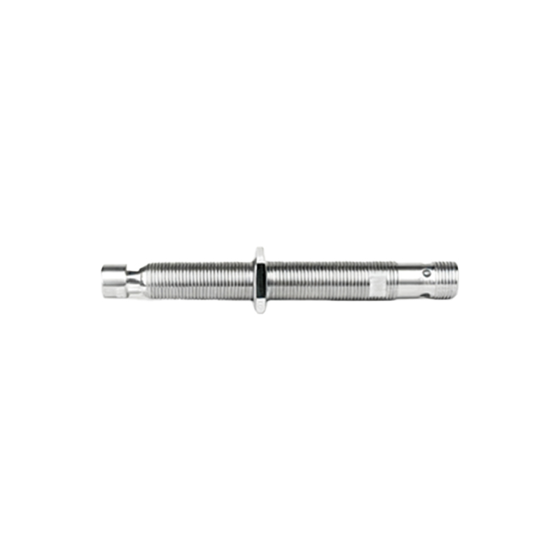
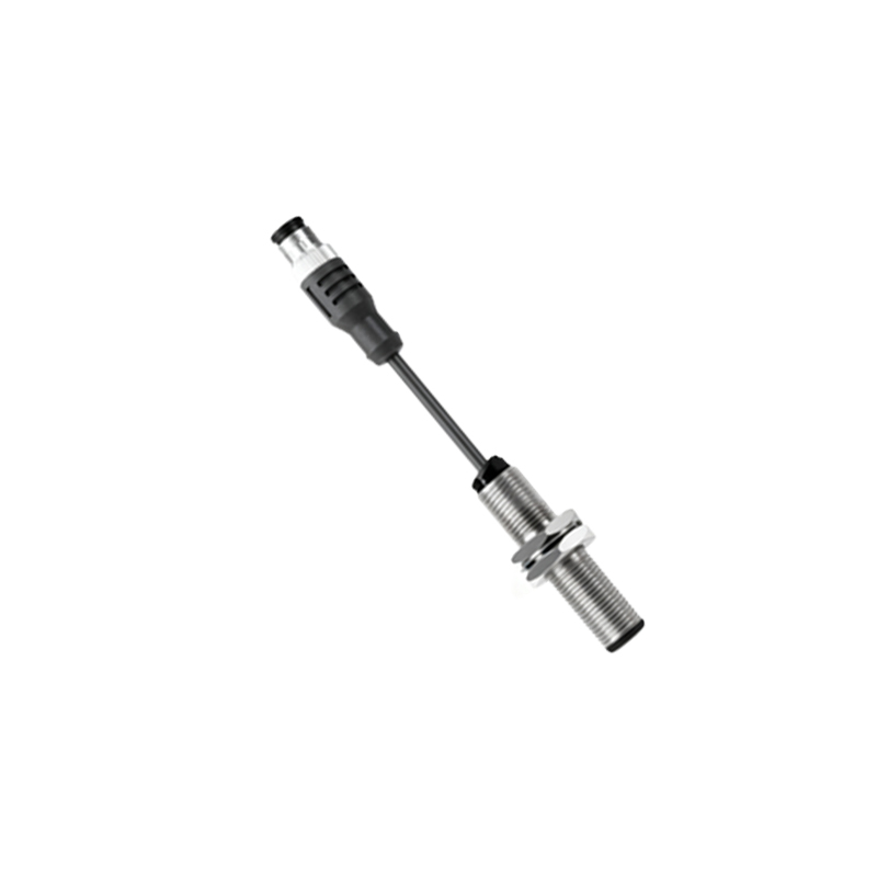
Before initiating any adjustment, a thorough preparatory phase is mandatory. First, de-energize the electrical circuit and lock out/tag out (LOTO) the power source to ensure absolute safety. Consult the sensor's datasheet to confirm its type (e.g., inductive, capacitive, ultrasonic), output configuration (PNP/NPN, NO/NC), and adjustment method. Visually inspect the sensor housing for damage, corrosion, or accumulated debris on the sensing face, as contamination can significantly reduce effective range. Identify the adjustment mechanism, which is typically a potentiometer accessed via a small screwdriver slot or a multi-position DIP switch bank. Have the correct target material—the actual object to be detected—ready for testing. Ensure the sensor is correctly mounted, as flush-mountable sensors require non-metallic surroundings to achieve their full Sn, whereas non-flush types have a larger inherent range.
Step-by-Step Adjustment Procedure
With preparations complete and safety protocols observed, power the sensor circuit. Begin with the sensitivity potentiometer set to its minimum (fully counter-clockwise) position. Slowly bring the standard target toward the sensor's sensing face along the central axis. Observe the sensor's output indicator LED (most models have one). At the point where the LED activates, marking the detection event, note the distance between the target and the sensor face. This is your current operating point. Now, gradually rotate the potentiometer clockwise to increase sensitivity. Move the target away until the LED deactivates, then bring it closer again to find the new, longer detection point. Repeat this process iteratively: adjust the potentiometer, then test with the target moving in and out. The goal is to set the detection distance slightly less than the required application distance, well within the Sa range. This provides a buffer against minor mechanical misalignments or buildup of dust. For sensors with teach-in functionality, follow the manufacturer's sequence (often involving a dedicated button press) to automatically calibrate to the present target distance.
Optimization and Troubleshooting Tips
Fine-tuning extends beyond basic distance setting. For inductive sensors detecting different metals, remember the reduction factor; stainless steel may require a sensor with a longer Sn or increased sensitivity. For capacitive sensors, adjust the sensitivity to ignore non-target materials like container walls while detecting the contents. Always test with the target under normal operational speeds, as very high speeds might require a shorter set distance to account for sensor response time. Common issues include unstable switching, which is often caused by electrical noise, vibration, or an overly sensitive setting. If instability occurs, slightly decrease the sensitivity. Failure to detect at the expected range can stem from using an incorrect target material, a misaligned target path, or a heavily contaminated sensing face. For sensors with a hysteresis setting, a wider hysteresis can prevent rapid on/off toggling when a target is at the threshold boundary, providing more stable output in presence detection applications.
Verification and Long-Term Stability
After adjustment, rigorous verification under simulated or actual operating conditions is critical. Perform at least 50 consecutive detection cycles to ensure consistent operation. Check for false triggers by moving non-target objects (like tools or operator hands) near the sensor's field. Monitor the sensor's performance over a range of ambient temperatures if applicable, as extreme cold or heat can affect the sensing distance. Document the final potentiometer position or DIP switch settings for future reference and easier replication. Implement a periodic maintenance schedule to clean the sensor face and verify the sensing distance, as environmental contaminants or mechanical drift over time can degrade performance. For critical applications, consider using sensors with built-in diagnostics or IO-Link capability, which provide detailed health and parameter data, enabling predictive maintenance and remote adjustment verification, thereby enhancing system reliability and uptime.