Understanding Proximity Sensor Failure Symptoms
When a proximity sensor malfunctions, it often exhibits clear warning signs. Common symptoms include erratic machine behavior, such as unexpected stops or starts, or failure to detect objects within its specified range. The sensor might output a constant signal regardless of target presence, or produce no signal at all. In automated systems, this can lead to production line jams, incorrect part placement, or safety hazards. Visual inspection can sometimes reveal physical damage like cracks in the housing, bent sensing faces, or corroded connectors. However, many failures are internal and not visible, necessitating systematic electrical and functional testing to confirm the issue.
Initial Diagnostic Steps and Safety Precautions
Before any troubleshooting, always de-energize and lock out the equipment to ensure safety. Begin with a basic visual and physical check. Inspect the sensor's mounting; loose brackets can misalign the sensor, causing unreliable operation. Check the cable for cuts, pinch points, or exposure to excessive heat or chemicals. Examine the connector for bent pins, moisture ingress, or corrosion. Verify that the sensing face is clean and free from obstructions like metal shavings, dirt, or paint buildup, which can attenuate the sensing field. Ensure the target object's material, size, and approach speed are within the sensor's published specifications, as using an incorrect target is a frequent cause of perceived failure.
Electrical Testing with a Multimeter
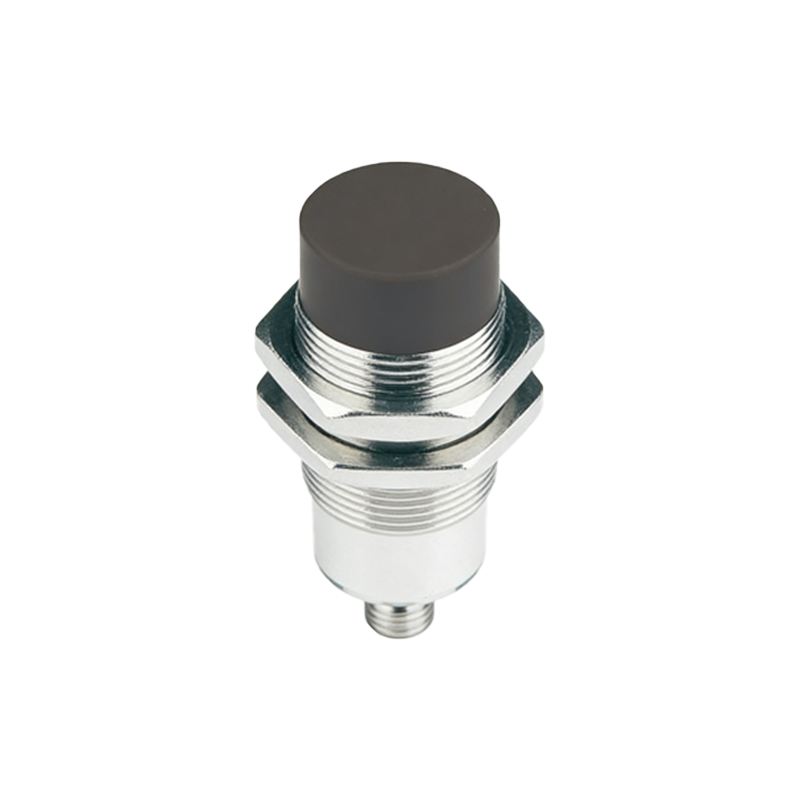
If visual checks are inconclusive, proceed with electrical measurements. For a 3-wire DC sensor, first confirm power supply voltage at the sensor terminals is stable and within tolerance (e.g., 24V DC ±10%). With power applied, use a digital multimeter to measure the output. For a normally open (NO) sensor, the voltage between the output wire and common should be near supply voltage when no target is present, and drop to a low voltage (typically<2V) when a valid target is brought into range. A constant high or low reading indicates a fault. For 2-wire AC/DC sensors, measure the voltage drop across the sensor or the current loop. Also, check for short circuits or excessive leakage current. Always consult the sensor's datasheet for specific test points and expected values.
Oscilloscope Analysis for Dynamic Issues
Intermittent faults or problems related to switching speed may require an oscilloscope. Connect the scope probe to the sensor's output line to observe the signal waveform. Look for clean, sharp transitions between on and off states. Signs of trouble include excessive noise on the signal line, slow rise/fall times, or signal oscillation (chatter). This chatter can be caused by electrical interference, a marginal sensing distance, or a failing internal component. The oscilloscope can also help diagnose issues with PWM outputs or analog sensors by verifying that the output signal correctly corresponds to the distance of the target. Shielding and grounding problems often manifest as high-frequency noise superimposed on the output signal.
Environmental and Interference Factors
Proximity sensors can fail due to harsh operating conditions. Extreme temperatures beyond the sensor's rating can cause drift or permanent damage. Strong magnetic fields from nearby motors or welding equipment can induce false signals in inductive sensors. Ultrasonic noise can affect capacitive sensors. Multiple sensors mounted close together might interfere with each other, a phenomenon known as mutual interference. Always ensure the sensor's environmental specifications (IP rating, temperature, EMI immunity) match the application. Sometimes, relocating the sensor, adding shielding, or installing a ferrite core on the cable can resolve interference-related failures without replacing the sensor.
Repair, Replacement, and Recalibration
Most solid-state proximity sensors are sealed units and cannot be repaired internally. If diagnostics confirm the sensor is faulty, replacement is the standard procedure. When installing a new sensor, ensure it is an exact match for the old one in terms of type (inductive, capacitive, magnetic), sensing distance, output configuration (PNP/NPN, NO/NC), voltage, and electrical connection. After installation, carefully adjust the mounting position and sensing distance. For adjustable sensors, use the manufacturer's recommended procedure and a precise target to set the sensitivity or switching point. Document the failure and the replacement for future maintenance records. In rare cases with specialized analog or programmable sensors, a recalibration using the manufacturer's software and tools may be necessary to restore functionality.
Implementing Preventive Maintenance Strategies
To minimize future failures, establish a proactive maintenance schedule. Regularly clean sensor faces and inspect for physical damage. Periodically check electrical connections for tightness and corrosion. Log environmental conditions like temperature