Understanding Proximity Sensor Basics
Proximity sensors, including inductive switches, are non-contact devices that detect the presence or absence of metallic objects within their sensing range. They are widely used in industrial automation, machinery safety, and process control systems. These sensors operate by generating an electromagnetic field; when a metal target enters this field, it induces eddy currents, causing the sensor to trigger an output signal. Common types include two-wire, three-wire, and four-wire configurations, each with specific wiring requirements. Proper installation ensures reliable performance, reduces downtime, and prevents electrical faults. Before wiring, always refer to the manufacturer's datasheet for voltage ratings, current limits, and environmental specifications.
Pre-Wiring Safety and Preparation
Safety is paramount when working with electrical components. Begin by disconnecting power to the circuit to avoid shocks or short circuits. Use appropriate personal protective equipment, such as insulated gloves and safety glasses. Gather necessary tools: wire strippers, screwdrivers, and a multimeter for testing. Check the sensor's model number to confirm its type (e.g., NPN or PNP for DC sensors, AC/DC compatibility). Ensure the power supply voltage matches the sensor's requirements—typically 10-30V DC for DC sensors or 20-250V AC for AC models. Inspect wires for damage and verify that the load (e.g., relay, PLC input) is compatible with the sensor's output current. Label wires clearly to avoid confusion during connection.
Wiring Two-Wire Proximity Sensors
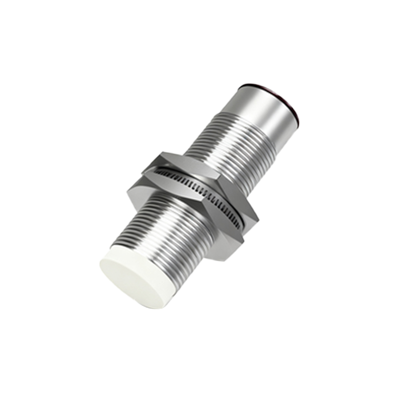
Two-wire sensors are simple to install, as they connect directly in series with the load and power supply. They function like a switch, with no separate power and output wires. For AC sensors, connect one wire to the live (hot) terminal of the power source and the other wire to the load. The load then links to the neutral line. For DC versions, ensure polarity is observed: typically, the brown wire goes to positive voltage, and the blue wire to negative. These sensors have a residual current when off, so the load must handle this leakage to prevent false triggering. Test the circuit by bringing a metal target near the sensor; the load should activate within the specified sensing distance.
Wiring Three-Wire Proximity Sensors
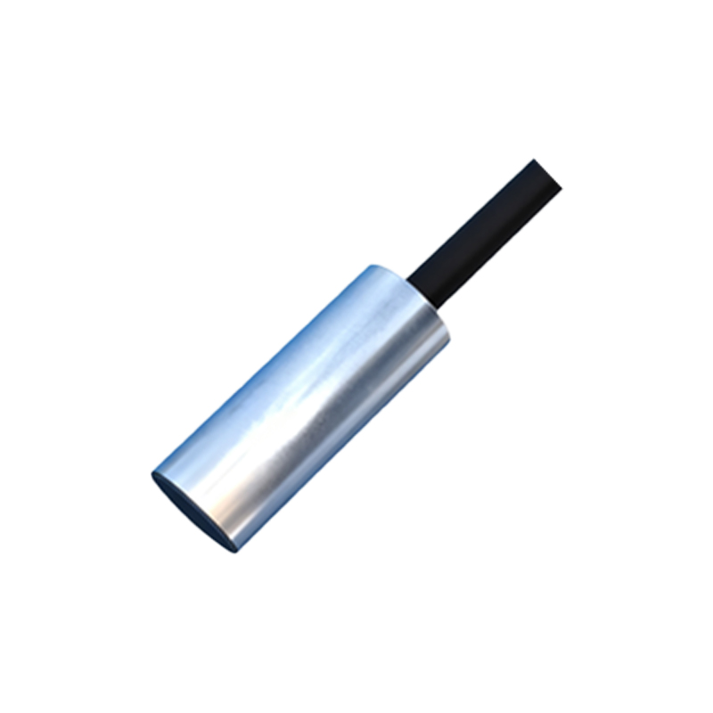
Three-wire sensors are common in DC applications and offer improved performance with separate power and output lines. They come in NPN (sinking) and PNP (sourcing) types. For a three-wire sensor, identify the wires: brown (positive), blue (negative), and black (output). For PNP sensors, connect brown to DC positive, blue to DC negative, and black to the load. The load's other terminal goes to negative. For NPN sensors, wire brown to positive, blue to negative, and black to the load, with the load's other terminal connected to positive. This configuration allows for low leakage current and faster switching. Always ground the sensor housing if specified, using a separate ground wire for noise reduction.
Wiring Four-Wire Proximity Sensors
Four-wire sensors provide dual outputs (e.g., normally open and normally closed) or complementary signals for complex control systems. Wires are typically color-coded: brown (positive), blue (negative), black (output 1), and white (output 2). Connect power wires as with three-wire sensors. For dual outputs, link each output wire to separate loads, ensuring the total current does not exceed the sensor's rating. Some models allow independent switching for different targets. Verify wiring against the datasheet diagram, as colors may vary by manufacturer. These sensors are ideal for applications requiring redundancy or multiple control points, such as conveyor systems or safety interlocks.
Testing and Troubleshooting Connections
After wiring, restore power and test the sensor with a metal target. Use a multimeter to check voltage at the output terminal: it should match the supply voltage when active (for PNP) or drop to near zero (for NPN). If the sensor fails to trigger, inspect connections for loose wires or incorrect polarity. Ensure the target is within the sensing range and made of suitable material (e.g., steel for inductive sensors). Environmental factors like moisture, vibration, or electrical noise can interfere with operation; shield cables and use ferrite cores if needed. For persistent issues, consult the manufacturer's troubleshooting guide or replace the sensor. Regular maintenance, including cleaning the sensing face, prolongs lifespan.
Best Practices for Optimal Performance
To maximize sensor reliability, follow industry best practices. Mount sensors securely using