Introduction to Proximity Photoelectric Sensors
Proximity photoelectric sensors are indispensable components in modern industrial automation, providing non-contact detection of objects. Their operation is based on the emission and reception of light, typically infrared, visible red, or laser. The electrical symbols used to represent these sensors in circuit diagrams and technical documentation are standardized to ensure clear communication across global engineering teams. Understanding these symbols is fundamental for designing, troubleshooting, and maintaining automated systems. This guide delves into the standard electrical symbols, their variations, and their practical implications in schematic design.
Standard IEC and ANSI Symbol Representations
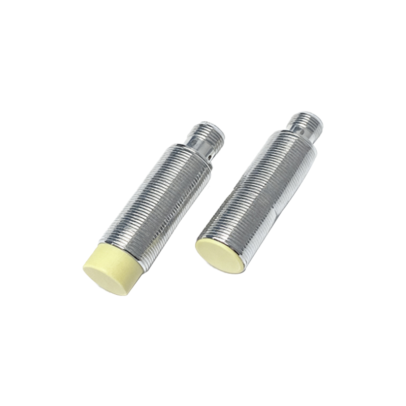
The most widely recognized symbols for photoelectric sensors are defined by the International Electrotechnical Commission (IEC) and the American National Standards Institute (ANSI). The base symbol often resembles a circle or a diamond shape with internal graphical elements indicating function. A common representation for a generic photoelectric sensor is a circle divided into two halves. The top half contains two inward-pointing arrows, symbolizing light emission. The bottom half features a photodiode or phototransistor symbol—a circle with two diagonal arrows pointing inward and a solid arrow pointing away, representing light reception and signal conversion. For proximity-specific types, this symbol is often enclosed within a square or rectangle, denoting a housed sensor unit with integrated electronics.
Symbol Variations for Different Sensing Modes
The core symbol adapts to represent the three primary sensing modes: through-beam, retro-reflective, and diffuse (proximity). For a through-beam sensor, the symbol may be split into two separate components: a standalone emitter symbol (circle with outward arrows) and a standalone receiver symbol. These are placed apart on the schematic, connected by dashed lines representing the light beam. The retro-reflective mode symbol often integrates the emitter and receiver into a single symbol, sometimes with a small graphical element representing a reflector. The diffuse or proximity mode symbol is typically a single unit, as the emitter and receiver are in the same housing, detecting light reflected directly from the target object.
Incorporating Electrical Connections and Outputs
The graphical symbol is always accompanied by terminal designations and output type indicators. Common terminals include +V (supply voltage), 0V (ground), and the output signal line. The output type is crucial and is indicated near the output terminal. For a PNP (sourcing) output, a small upward-pointing arrow or the annotation "PNP" is used. For an NPN (sinking) output, a downward-pointing arrow or "NPN" is shown. Solid-state relay (SSR) or analog output symbols may also be integrated. The output symbol is often a switch contact (normally open or normally closed) placed within or adjacent to the main sensor symbol, clearly depicting the switching action upon detection.
Reading Sensor Datasheets and Symbol Correlation
Engineering datasheets provide the definitive reference for a sensor's electrical symbol. Manufacturers include a detailed "Connection Diagram" section that shows the exact symbol, terminal numbering, wire color coding, and recommended connection to a programmable logic controller (PLC) or other control devices. It is vital to cross-reference the schematic symbol with the datasheet, as some manufacturers use slight variations or proprietary additions. The datasheet will also specify if the sensor features a light-on/dark-on operation mode, which may be indicated by a small "L.On" or "D.On" notation on the output line of the symbol.
Practical Application in Circuit Design
When integrating a proximity photoelectric sensor into a control circuit, the electrical symbol serves as a blueprint. The designer must correctly connect the power supply lines and interface the output with the load, such as a PLC input module, relay coil, or indicator lamp. For example, connecting a PNP sensor's output to an NPN-compatible PLC input will cause malfunction. The symbol, with its clear output type marking, prevents such errors. Furthermore, symbols for sensors with built-in timers, logic functions, or diagnostic outputs (e.g., IO-Link) include additional graphical blocks to represent these advanced features, guiding the designer in utilizing all capabilities.
Common Pitfalls and Best Practices
A frequent error is misinterpreting the output type from an ambiguous symbol. Always verify against the manufacturer's documentation. Another pitfall is neglecting the load connection diagram, especially for 3-wire DC sensors. Best practice involves using consistent symbol libraries within Computer-Aided Design (CAD) software for electrical schematics. Label each sensor symbol with a unique reference designator (e.g., B1, B2 for sensors) and, if space allows, a brief functional description. This enhances schematic readability and aids