Understanding Proximity Switch Length Measurement Sensors
Proximity switch length measurement sensors, often called "metering" or "measuring wheel" sensors, are fundamental components in industrial automation for accurately measuring linear material lengths, such as wire, cable, fabric, or paper. These systems typically integrate a rotary encoder attached to a measuring wheel with a proximity switch that detects the wheel's rotation or specific markers. The proximity switch acts as the primary sensing element, providing a digital pulse for each unit of rotation. Correct wiring is paramount for ensuring signal integrity, measurement accuracy, and system reliability. This guide details the standard wiring procedures for common DC 3-wire and 2-wire proximity switch configurations within these measurement systems.
Essential Components and Pre-Wiring Checklist
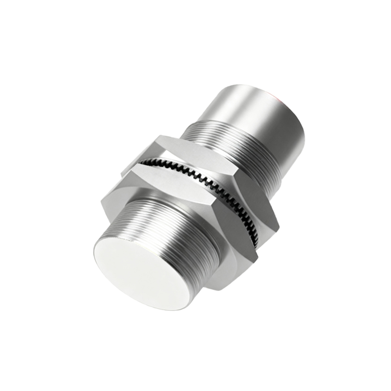
Before beginning the wiring process, ensure you have all necessary components: the proximity sensor itself, the measuring wheel/encoder assembly, a suitable DC power supply (commonly 10-30V DC), the receiving device (like a PLC counter input, frequency converter, or dedicated length controller), and appropriate cables. Always consult the manufacturer's datasheet for the specific sensor model to verify its electrical characteristics, including operating voltage, output type (PNP or NNP sinking/sourcing), current rating, and wiring diagram. Safety is critical; disconnect all power sources before handling any wires. Verify the mechanical installation of the measuring wheel and sensor, ensuring proper gap alignment as specified to guarantee consistent pulse generation.
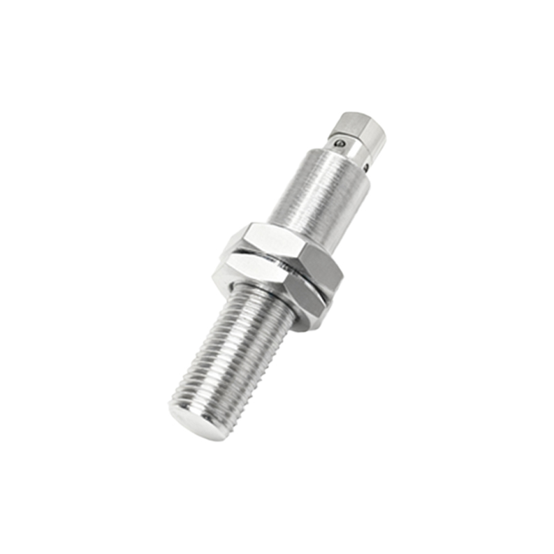
Wiring a 3-Wire DC Proximity Sensor (PNP Output)
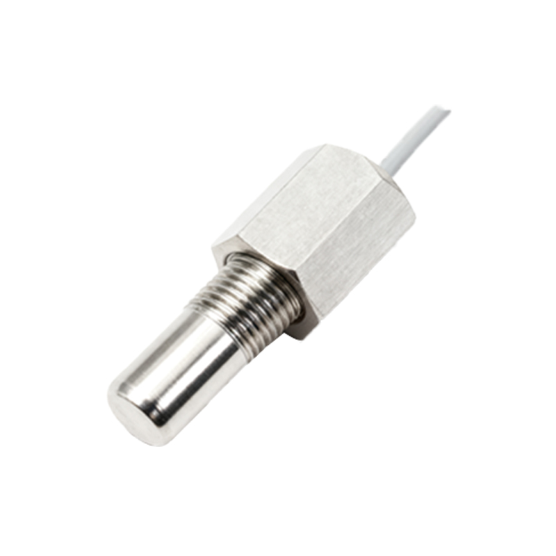
The 3-wire DC sensor is the most prevalent type in modern systems. For a PNP (sourcing) output sensor, the three wires are typically brown, blue, and black. Connect the brown wire to the positive terminal (+) of your DC power supply (e.g., +24V). Connect the blue wire to the negative terminal (-) or common ground (0V) of the power supply. The black wire is the switched output signal. This wire must be connected to the input channel of your receiving device (e.g., PLC digital input). The receiving device's input common for that channel must also be connected to the power supply's 0V (ground). When the sensor detects the target on the measuring wheel, it switches the black wire to supply +24V to the PLC input, signaling a pulse. Always install a suppression diode or a small value fuse for protection if recommended.
Wiring a 3-Wire DC Proximity Sensor (NPN Output)
For an NPN (sinking) output sensor, the wire colors are usually the same: brown for positive, blue for negative, and black for output. The connection for brown and blue wires remains identical: brown to DC+ and blue to DC-. The critical difference lies in the black output wire and the receiving device's configuration. The black wire from the sensor is connected to the PLC input channel. However, for an NPN sensor, the PLC input's common point must be connected to the positive supply (+24V). When activated, the NPN sensor sinks current, connecting the black wire to 0V, thereby completing the circuit to ground through the PLC input. Mismatching PNP and NPN wiring with the controller will result in no signal.
Wiring a 2-Wire DC Proximity Sensor
Two-wire sensors are simpler, functioning similarly to a switch in series with the load. They have two wires, typically brown and blue. These sensors can be connected in either polarity for AC models, but DC models require correct polarity. For DC systems, connect one wire (often brown) to the positive side of the power supply. Connect the other wire (blue) to one side of the load (the PLC input). The other side of the PLC input is then connected to the power supply's negative terminal. It is crucial to ensure that the sensor's leakage current in the "off" state is below the PLC input's minimum OFF-state current requirement to prevent false triggering. A bypass resistor may sometimes be necessary.
Connecting to the Measurement and Control System
Once the sensor is powered and wired, its output must be correctly integrated. The pulses from the proximity switch are fed into a high-speed counter input on a PLC or a dedicated length measurement module. The system's program calculates length based on the pulse count and a preset pulses-per-meter (or pulses-per-revolution) factor derived from the measuring wheel's circumference. For long cable runs, use shielded cables and connect the shield to a proper earth ground at one end only (usually the control panel end) to minimize electromagnetic interference (EMI) which can cause counting errors. Ensure the