Introduction to Proximity Switch Speed Sensors
Proximity switch speed sensors are widely used in industrial automation for monitoring rotational or linear speed. These non-contact devices detect the presence of metallic objects, such as gear teeth or encoder discs, and generate electrical pulses corresponding to the speed of the target. They offer high reliability, durability, and precision, making them ideal for applications in conveyors, motors, and machinery where accurate speed measurement is critical. Understanding the wiring diagram is essential for proper installation, ensuring optimal performance and safety in various operational environments.
Key Components and Their Functions
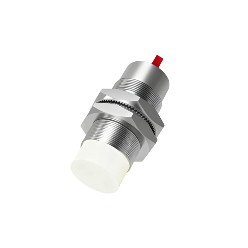
A typical proximity switch speed sensor system consists of several key components. The sensor itself, often an inductive or capacitive type, detects metallic targets and converts the proximity into an electrical signal. The power supply provides the necessary voltage, usually ranging from 10-30V DC, to operate the sensor. Output wires, including positive, negative, and signal lines, transmit the pulse data to a controller or display unit. Additionally, shielding and grounding elements are crucial to minimize electrical noise and interference, which can affect accuracy. Each component must be correctly connected as per the wiring diagram to ensure seamless integration into the control system.
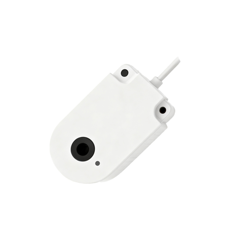
Standard Wiring Diagram Overview
The wiring diagram for a proximity switch speed sensor typically follows a standard configuration. The positive wire (often brown or red) connects to the positive terminal of the power supply, while the negative wire (blue or black) links to the ground. The signal output wire (black or white) is routed to the input of a PLC, frequency converter, or speed monitor. In some models, a separate wire may be used for diagnostic or enable functions. Diagrams also include symbols for protective devices like fuses or surge suppressors to safeguard against voltage spikes. It's vital to refer to the manufacturer's specific diagram, as variations exist based on sensor type and output (e.g., NPN or PNP).
Step-by-Step Wiring Instructions
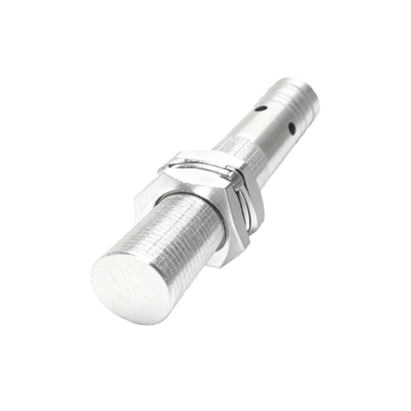
To wire a proximity switch speed sensor, start by disconnecting all power sources to prevent electrical hazards. Identify the sensor wires using the provided color codes or labels. Connect the positive wire to the DC power supply's positive terminal and the negative wire to the ground. Attach the signal output wire to the designated input on the control device. Ensure all connections are secure and insulated to avoid short circuits. If the sensor includes a shield wire, ground it at one end to reduce electromagnetic interference. After wiring, double-check the diagram for accuracy, then apply power and test the sensor by moving a metallic target nearby to verify pulse generation.
Common Wiring Configurations and Variations
Proximity switch speed sensors come in different wiring configurations to suit various applications. Two-wire sensors combine power and signal in a single loop, simplifying installation but may have lower accuracy. Three-wire sensors, the most common, separate power and signal for better performance and are available in NPN (sinking) or PNP (sourcing) outputs, depending on the load connection. Four-wire sensors add an additional output for redundancy or dual signals. Some advanced models include analog outputs or IO-Link communication for enhanced data transmission. Always consult the wiring diagram to match the configuration with your system's requirements, such as voltage levels and signal compatibility.
Troubleshooting Wiring Issues
If a proximity switch speed sensor fails to operate correctly, wiring problems are a common cause. Check for loose or corroded connections at terminals and ensure wires are not damaged or pinched. Verify the power supply voltage matches the sensor's specifications using a multimeter. Incorrect polarity or reversed wires can lead to malfunction, so cross-reference with the diagram. Electrical noise from nearby equipment may interfere with the signal; consider adding ferrite cores or relocating wires away from high-voltage cables. If the sensor does not detect targets, inspect the sensing distance and alignment, as these can affect performance even with proper wiring.
Safety and Best Practices
Safety is paramount when wiring proximity switch speed sensors. Always follow lockout-tagout procedures to de-energize equipment before installation. Use appropriate personal protective equipment, such as insulated gloves and goggles. Adhere to local electrical codes and standards, like IEC or NEC, for wiring practices. Route cables in conduits or cable trays to protect them from physical damage and environmental factors like moisture or chemicals. Regularly inspect connections for wear and maintain clear documentation of wiring diagrams for future reference. Implementing these best practices ensures reliable operation and reduces the risk of accidents or downtime in industrial settings.
Applications and Benefits
Proximity switch speed sensors are employed in diverse industries, including manufacturing, automotive,